Using contact and open collector outputs – Yaskawa Matrix Converter User Manual
Page 386
10
-16
Using Contact and Open Collector Outputs
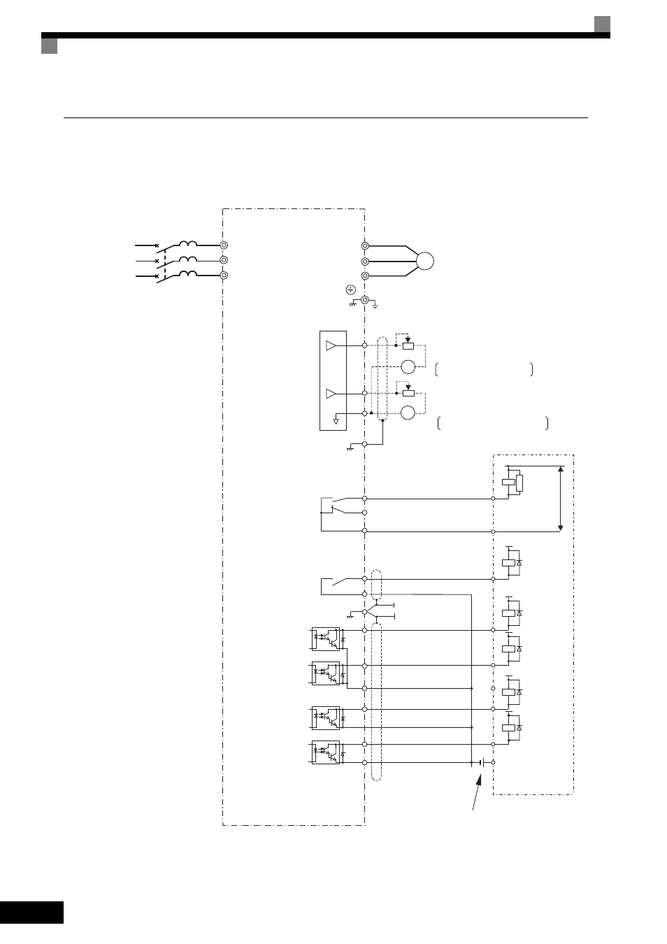
This example shows wiring for digital outputs and open collector outputs.
The following example is for the CIMR-ACA25P5 (200 V class MxC for 5.5 kW).
Fig 10.8
MxC
U/T1
V/T2
W/T3
IM
Ground
MA
MB
MC
P2
PC
Multi-function
open collector output
48 Vdc 50 mA max
P1
(Default: zero speed)
M1
M2
Multi-function contact output
(Default: RUN)
T/L3
S/L2
R/L1
3-phase power
MCCB
T
S
R
FM
Multi-function analog output 1
AC
E(G)
-10 to +10 V 2 mA
AM
FM
㧗
㧗
㧙
㧙
Default: Output frequency,
0 to +10 V
Default: Ouput current,
0 to +10 V
-10 to +10 V 2 mA
Multi-function analog output 2
Frequency meter scale adjustment resistor
20 k
ǡ
Ammeter scale adjustment resistor
20 k
ǡ
Motor
Sequence external power
supply
SA
250 Vac max
30 Vdc max
Flywheel
diode
48 Vdc max
48 Vdc max
Sequence
(Default: Freq agree)
250 Vac, 10 mA min. 1 A max
30 Vdc, 10 mA min. 1 A max
250 Vac, 1 A max
30 Vdc, 1 A max
E(G)
Flywheel
diode
Flywheel
diode
Open collector 2
AM
P4
C4
P3
C3
48 Vdc max
48 Vdc max
Flywheel
diode
Flywheel
diode
Error contact output
Open collector 1