Yaskawa Matrix Converter User Manual
Page 113
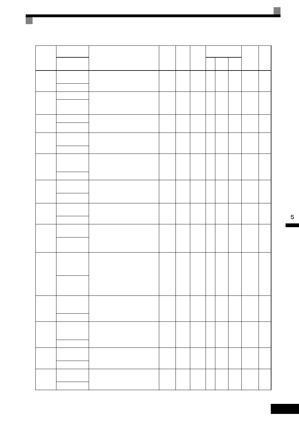
Parameter Tables
5-
13
b5-04
Integral Limit
Setting
Sets the I-control limit as a percentage of
the maximum output frequency.
0.0 to
100.0
100.0
%
Yes
A
A
A
1A8H
6-95
PID I Limit
b5-05
Derivative Time
Sets D-control derivative time in 1-sec-
ond units.
D-control is not performed when the set-
ting is 0.00.
0.00 to
10.00
0.00 s
Yes
A
A
A
1A9H
6-95
PID D Time
b5-06
PID Output Limit Sets the upper limit after PID-control as a
percentage of the maximum output fre-
quency.
0.0 to
100.0
100.0
%
Yes
A
A
A
1AAH
6-95
PID Limit
b5-07
PID Offset
Adjustment
Sets the offset after PID-control as a per-
centage of the maximum output fre-
quency.
-100.0
to
+100.0
0.0%
Yes
A
A
A
1ABH
6-95
PID Offset
b5-08
PID Primary
Delay Time
Constant
Sets the time constant for low pass filter
for PID-control outputs in 1-second units.
Not usually necessary to set.
0.00 to
10.00
0.00 s
Yes
A
A
A
1ACH
6-95
PID Delay Time
b5-09
PID Output Level
Selection
Select forward/reverse for PID output.
0: PID output is forward.
1: PID output is reverse (highlights the
output code)
0 or 1
0
No
A
A
A
1ADH
6-95
Output Level Sel
b5-10
PID Output Gain
Setting
Sets output gain.
0.0 to
25.0
1.0
No
A
A
A
1AEH
6-95
Output Gain
b5-11
PID Output
Reverse Selection
0: 0 limit when PID output is negative.
1: Reverses when PID output is nega-
tive.
0 limit when reverse prohibit is selected
using b1-04.
0 or 1
0
No
A
A
A
1AFH
6-95
Output Rev Sel
b5-12
PID Feedback
Reference Miss-
ing Detection
Selection
0: No detection of loss of PID feedback.
1: Detection of loss of PID feedback.
Operation continues during detection,
with the malfunctioning contact not
operating.
2: Detection of loss of PID feedback.
Coasts to stop during detection, and
fault contact operates.
0 to 2
0
No
A
A
A
1B0H
6-96
Fb los Det Sel
b5-13
PID Feedback
Loss Detection
Level
Sets the PID feedback loss detection level
as a percent units, with the maximum out-
put frequency at 100%.
0 to 100
0%
No
A
A
A
1B1H
6-96
Fb los Det Lvl
b5-14
PID Feedback
Loss Detection
Time
Sets the PID feedback loss detection level
in s units.
0.0 to
25.5
1.0 s
No
A
A
A
1B2H
6-96
Fb los Det Time
b5-15
PID Sleep Func-
tion Start Level
Set the PID sleep function start level as a
frequency.
0.0 to
120.0
0.0 Hz
No
A
A
A
1B3H
6-96
PID Sleep Level
b5-16
PID Sleep Delay
Time
Set the delay time until the PID sleep
function starts in seconds.
0.0 to
25.5
0.0 s
No
A
A
A
1B4H
6-96
PID Sleep Time
Parameter
Number
Name
Description
Setting
Range
Default
Change
during
Run
Control
Methods
MEMO-
BUS
Register
Page
Display
V/f
Open
Loop
Vector
Flux
Vector