Yaskawa Matrix Converter User Manual
Page 43
Wiring Main Circuit Terminals
2-
9
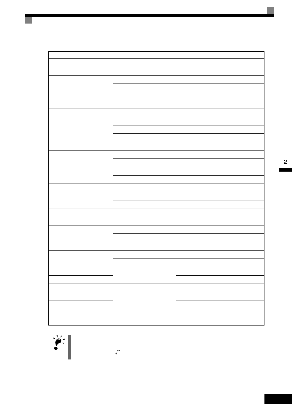
Table 2.3 Closed-Loop Connector Sizes (JIS C2805) (200 V class and 400 V class)
Wire Thickness (mm
2
)
Terminal Screws
Size
0.5
M3.5
1.25 to 3.5
M4
1.25 to 4
0.75
M3.5
1.25 to 3.5
M4
1.25 to 4
1.25
M3.5
1.25 to 3.5
M4
1.25 to 4
2
M3.5
2 to 3.5
M4
2 to 4
M5
2 to 5
M6
2 to 6
M8
2 to 8
3.5/5.5
M4
5.5 to 4
M5
5.5 to 5
M6
5.5 to 6
M8
5.5 to 8
8
M5
8 to 5
M6
8 to 6
M8
8 to 8
14
M6
14 to 6
M8
14 to 8
22
M6
22 to 6
M8
22 to 8
30/38
M8
38 to 8
50/60
M8
60 to 8
M10
60 to 10
80
M10
80 to 10
100
100 to 10
100
M12
100 to 12
150
150 to 12
200
200 to 12
325
M12 x 2
325 to 12
M16
325 to 16
IMPORTANT
Determine the wire gauge for the main circuit so that line voltage drop is within 2% of the rated voltage. Line
voltage drop is calculated as follows:
Line voltage drop (V) =
×
wire resistance (W/km)
×
wire length (m)
×
current (A)
×
10
-3
3