Yaskawa Matrix Converter User Manual
Page 384
10
-14
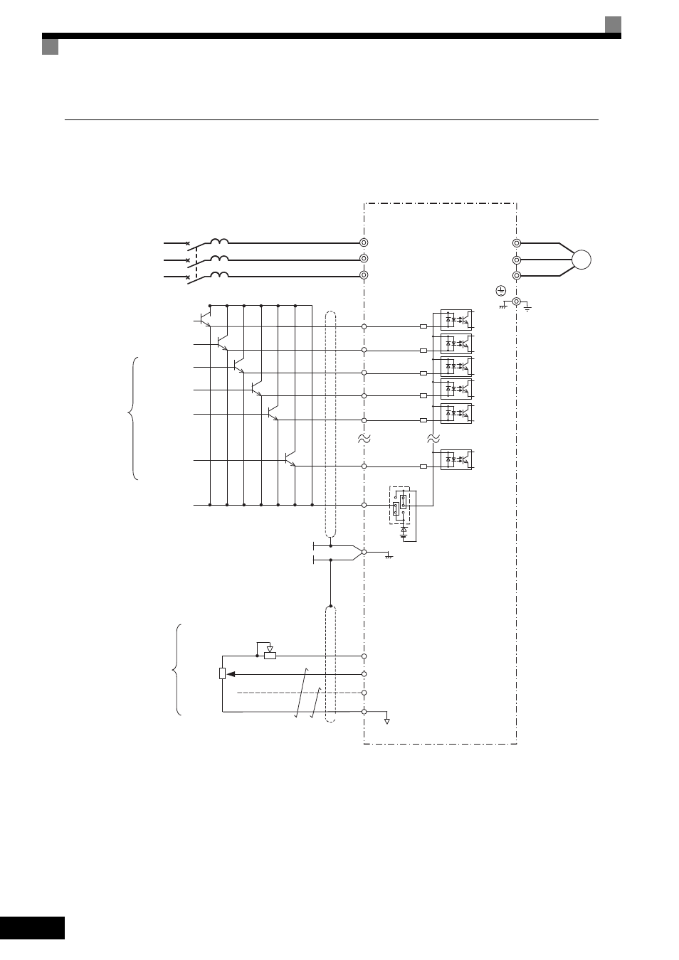
Using Transistors for Input Signals and a +24 V Common in Sourcing Mode
Set CN5 (shunt connector) on the control board to PNP as shown below for a sequence that uses a PNP tran-
sistor for an input signal (+24 V common and Sourcing Mode) and an internal +24 V power supply.
Fig 10.6
MxC
U/T1
V/T2
W/T3
IM
Ground
4 to 20 mA
0 to +10 V
+V
A1
A2
AC
0 V
Frequency
setter
2 k
Ω
External
frequency
references
2 k
Ω
2
1
3
3-phase power
T/L3
S/L2
R/L1
MCCB
T
S
R
E(G)
Shield wire
connection terminal
+24 V 8 mA
Motor
Multi-step
speed setting 1
Not used
Forward Run/Stop
Reverse Run/Stop
External fault
Fault reset
S5
S12
SC
S1
S2
S3
S4
Multi-function
contact inputs
(Default)
CN5
(PNP setting)
+24 V
0 to 10 V (20 k
Ω)
4 to 20 mA (250
Ω)
0 to 10 V (20 k
Ω) input
Frequency setting power
+15 V 20 mA
Master speed reference
Master speed reference
Frequency setting
adjustment