Quick programming mode and available parameters – Yaskawa Matrix Converter User Manual
Page 104
5
-4
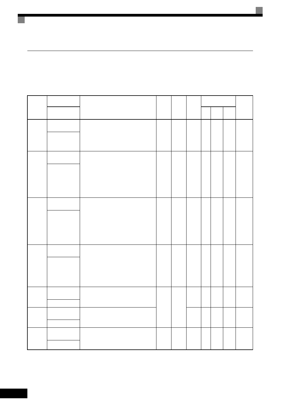
Quick Programming Mode and Available Parameters
The minimum parameters required for MxC operation can be programmed and monitored in the Quick Pro-
gramming Mode. The parameters displayed in the Quick Programming Mode are listed in the following table
(more parameters are available in the Advanced Programming Mode).
Refer to the illustration of menus and modes on page 3-5 for an overview of Quick Programming Mode.
Parameter
Number
Name
Description
Setting
Range
Default
Change
during
Run
Control
Methods
MEMO-
BUS
Register
Display
V/f
Open
Loop
Vector
Flux
Vector
A1-02
Control Method
Selection
Selects the Control Method.
0: V/f Control Method without a PG encoder
2: Open Loop Vector
3: Flux Vector (Closed Loop Vector)
This parameter is not initialized by the initialize
operation.
0, 2, or
3
2
No
Q
Q
Q
102H
Control Method
b1-01
Frequency Refer-
ence Selection
Selects the frequency reference input source.
0: Operator - Digital preset speed U1-01 or d1-
01 to d1-17.
1: Terminals - Analog input terminal A1 (or
terminal A2 based on parameter H3-09).
2: Serial Com - Modbus RS-422/485 terminals
R+, R-, S+, and S-.
3: Option PCB - Option card connected on
2CN.
0 to 3
1
No
Q
Q
Q
180H
Reference Source
b1-02
Run Command
Selection
Selects the Run Command input source.
0: Operator - RUN and STOP keys on digital
operator.
1: Terminals - Contact closure on terminals S1
or S2.
2: Serial Com - Modbus RS-422/485 terminals
R+, R-, S+, and S-.
3: Option PCB - Option card connected on
2CN.
0 to 3
1
No
Q
Q
Q
181H
Run Source
b1-03
Stopping Method
Selection
Selects the stopping method when the Run
Command is removed.
0: Decelerate to stop
1: Coast to Stop
2: DC Injection to Stop
3: Coast with Timer (A new Run Command is
ignored if received before the timer
expires).
0 to 3
*1
0
No
Q
Q
Q
182H
Stopping Method
C1-01
Acceleration Time
1
Sets the time to accelerate from zero to maxi-
mum frequency.
0.0 to
6000.0
*2
10.0 s
Yes
Q
Q
Q
200H
Accel Time 1
C1-02
Deceleration Time
1
Sets the time to decelerate from maximum fre-
quency to zero.
Yes
Q
Q
Q
201H
Decel Time 1
C6-02
Carrier Frequency
Selection
Select carrier frequency
2: 4.0 kHz
4: 8.0 kHz
6: 12.0 kHz
2, 4,
or 6
*3
2
No
Q
Q
Q
224H
CarrierFreq Sel