Yaskawa Matrix Converter User Manual
Page 48
2
-14
Wiring the Output Side of the Main Circuit
Observe the following precautions when wiring the main output circuits.
Connecting the MxC and Motor
Connect output terminals U, V, and W to motor lead wires U, V, and W, respectively.
Make sure the motor rotates forward when the Forward Run Command is given. Switch over any two of the
output terminals to each other and reconnect if the motor rotates in reverse with the Forward Run Command.
Never Connect a Power Supply to Output Terminals
Never connect a power supply to output terminals U, V, and W. Applying voltage to the output terminals will
damage circuitry in the MxC.
Never Short or Ground Output Terminals
If you touch the output wires with your bare hands, or if the output wires come into contact with the MxC cas-
ing, an electric shock or grounding will occur. This is extremely hazardous. Do not short the output wires.
Do Not Use a Phase Advancing Capacitor or Noise Filter
Never connect a phase advancing capacitor or general (LC/RC) noise filter to an output circuit. The high-fre-
quency components of the MxC output may result in overheating or damage to these parts, or may result in
damage to the MxC or cause other parts to burn.
Do Not Use an Electromagnetic Switch
Never connect an electromagnetic switch (MC) between the MxC and motor and then cycle power while the
MxC is running. If the MC is turned on while the MxC is operating, a large current inrush will trigger overcur-
rent or overvoltage protection.
When using an MC to switch over to a commercial power supply, stop the MxC and motor before operating
the MC. Use the speed search function if the MC is either open or closed while running. If action must be
taken to handle any momentary interruption in power, use a delayed release MC.
Installing a Thermal Overload Relay
This MxC has an electronic thermal protection function to protect the motor from overheating. If a multi-pole
motor is used, always install a thermal relay (THR) between the MxC and the motor, then set L1-01 to 0 (no
motor protection). The sequence should be designed so that the thermal overload relay contacts turn off the
magnetic contactor on the main circuit inputs.
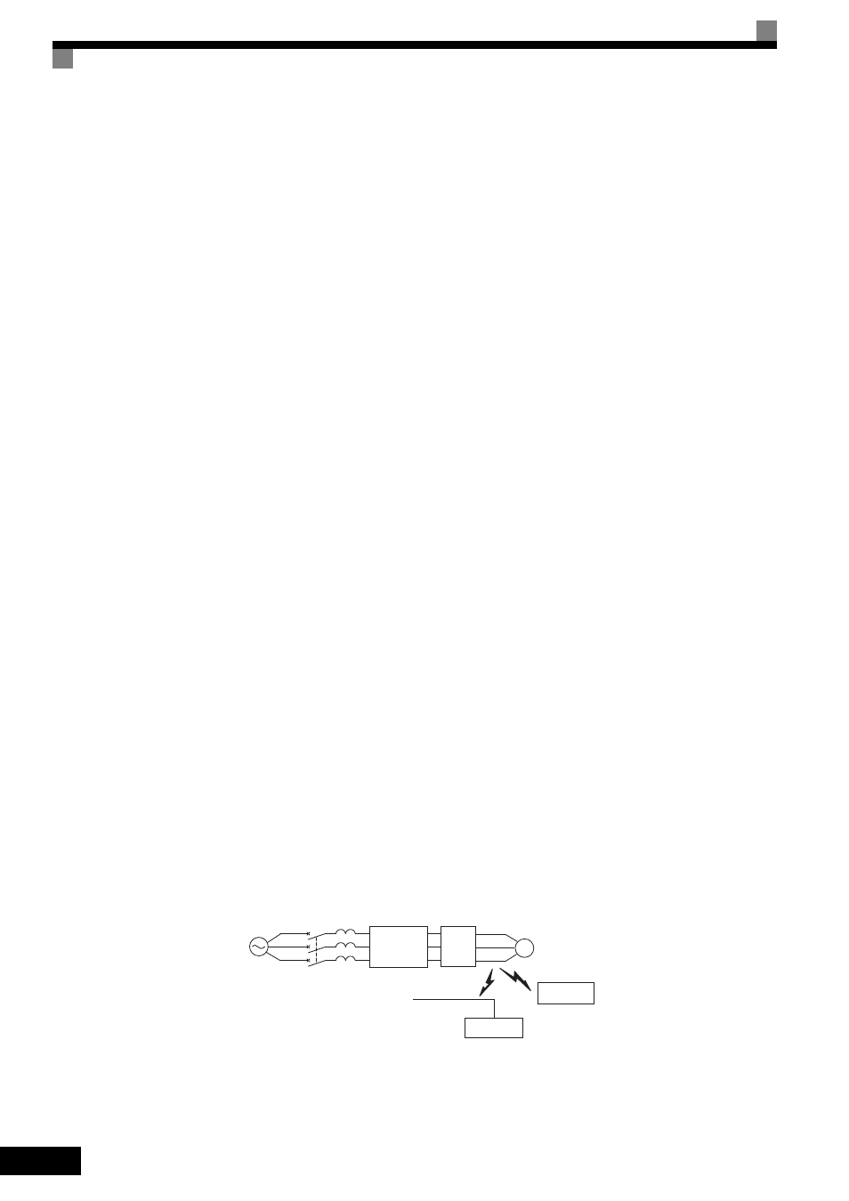
Installing a Noise Filter on Output Side
Connect a noise filter to the output side of the MxC to reduce radio noise and inductive noise. Refer to Chap-
ter 9 Specifications for details.
Fig 2.12 Installing a Noise Filter on the Output Side
Inductive Noise: Electromagnetic induction generates noise on the signal line, and may cause the controller to malfunction.
Radio Noise: Electromagnetic waves from the MxC and cables can cause the broadcasting radio receiver to make noise.
IM
MCCB
Power
supply
Noise
filter
Signal line
Inductive
noise
Radio noise
AM radio
Controller
MxC