Connection diagram – Yaskawa Matrix Converter User Manual
Page 37
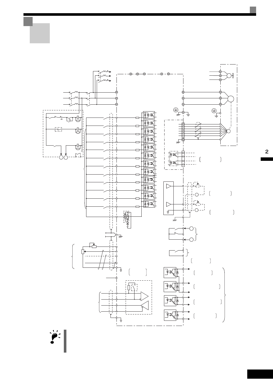
Connection Diagram
2-
3
Connection Diagram
The connection diagram of the MxC is shown in Fig 2.2.
When using the digital operator, the motor can be operated by wiring only the main circuits.
Fig 2.2 Connection Diagram (Model: CIMR-ACA2011)
IMPORTANT
* 1. Connect to the momentary power loss compensation unit. Do not connect power lines to these terminals.
* 2. Normally not used. Do not connect power lines to these terminals.
* 3. The MxC models CIMR-ACA4110 and 4160 do not have terminals r2, s2, t2, p1 and n1.
1
IG
R
IM
IM
2
PG
SA
SA
SA
S
T
1MCCB
MC
2MCCB
r1
s1
t1
r2
s2
t2
p1
n1
*1 *3
*2 *3
*2 *3 *2 *3
*1 *3
R/L1
S/L2
T/L3
U/T1
V/T2
W/T3
U
V
W
r1
s1
t1
PG-B2
TA1
3
4
5
6
TA3
TA2
1
2
3
4
S1
S2
S3
S4
S5
S6
S7
S8
S9
S10
S11
S12
SC
E(G)
+24V
8mA
+V
A1
A2
A3
AC0V
-V (-15V 20mA)
R+
R-
S+
S-
+24V
AM
FM
AC
MA
MC
E(G)
MA
MB
MC
M1
M2
P1
P2
PC
P3
C3
MC
On
MC
Off
THRX
2MCCB
THRX
TRX
MC
TRX
MA
MC
FU
FV
FW
-
+
-
+
1
2
3
C
H
B
G
A
F
D
P4
C4
3-phase power
200 V to 220 V
50/60 Hz
Motor
Cooling fan
Pulse monitor output
Wiring distance:
30 m max
Shielded twisted-pair
wires
Pulse B
Pulse A
(Ground to 100 max)
(optional)
MxC
CIMR-ACA2011
CN5 (NPN setting)
Multi-function analog output 1
FM
-10 to 10 V 2 mA
Default: Output frequency
0 to +10 V
Default: Output curren
0 to +10 V
-10 to 10 V 2 mA
Multi-function analog output 2
Ammeter adjustment
20 k
W
Ammeter adjustment
20 k
W
AM
Error contact output
250 VAC, 10 mA min. 1 A max
30 VAC, 10 mA min. 1 A max
Multi-function contact oputput
250 VAC, 10 mA min. 1 A max
30 VAC, 10 mA min. 1 A max
Default: Running
signal
Open collector 1
Open collector 2
Open collector 3
Open collector 4
Multi-function
open-collector
outputs
48 VDC
50 mA max
Default: Frequency
agree signal
Default: Zero
speed
Default:
Minor fault
Default:
MxC operation ready
MEMOBUS
communications
RS-485/422
Shield wire
connection terminal
Master speed
pulse train
Frequency setting power
Master speed reference
Multi-function anlog input
Master speed reference
4 to 20 mA (250
W
)
[0 to 10 V (20 k
W
) input]
+15 V, 20 mA
0 to 10 V (20 k
W
)
0 to 10 V (20 k
W
)
Terminating
resistance
Default:
Auxiliary frequency
command
0 to 32 kHz (3 k
W
)
High level: 3.5 to 13.2 V input
P
P
4 to 20 mA
0 to 10 V
0 to 10 V
Frequency
Frequency
setting
adjustment
setter
External
frequency
references
P
2 k
W
2 k
W
(Main speed switching)
External
baseblock command
Multi-step speed
reference 3
Multi-step speed
reference 4
Acc/dec time 1
Emergency stop (NO)
Forward Run/Stop
Reverse Run/Stop
External fault
Fault reset
Multi-step speed
reference 1
Multi-step speed
reference 2
Jog frequency
selection
contact inputs
Multi-function
(Default)
Fault contact
Thermal overload relay
(trip contact) for cooling fan
30 mA max