Yaskawa Matrix Converter User Manual
Page 106
5
-6
* 1. 0 or 1 for Flux Vector Control.
* 2. The setting range for accel/decel times depends on the setting of C1-10 (Accel/Decel Time Setting Units). If C1-10 is set to 0, the setting range is 0.00 to 600.00
(s).
* 3. Fixed to 2:4 kHz for V/f.
For Open Loop Vector Control, can select from 2:4 kHz or 4:8 kHz (Fixed to 2: 4 kHz for 200 V class MxC for 45 kW and 400 V class MxCs for 22 kW and
45 kW).
* 4. The default will change when the control method is changed. The Open Loop Vector defaults is given.
* 5. These are values for a 200 V class MxC. Values for a 400 V class MxC are double.
* 6. E1-13 is set to the same value as E1-05 by Auto-Tuning.
* 7. The setting range is from 10% to 200% of the MxC rated output current. The value for a 200 V class MxC for 5.5 kW is given.
* 8. The defaults depend on the MxC capacity. The values for a 200 V class MxC for 5.5 kW are given.
* 9. The FM output can be adjusted when the H4-02 or H4-03 setting is displayed in Quick, Advanced, or Verify Mode while the motor is stopped.
The AM output can be adjusted when the H4-05 or H4-06 setting is displayed in Quick, Advanced, or Verify Mode while the motor is stopped.
For analog output, the value equivalent to 100% of output value of monitored item is multiplied by the gain setting and the set bias is added.
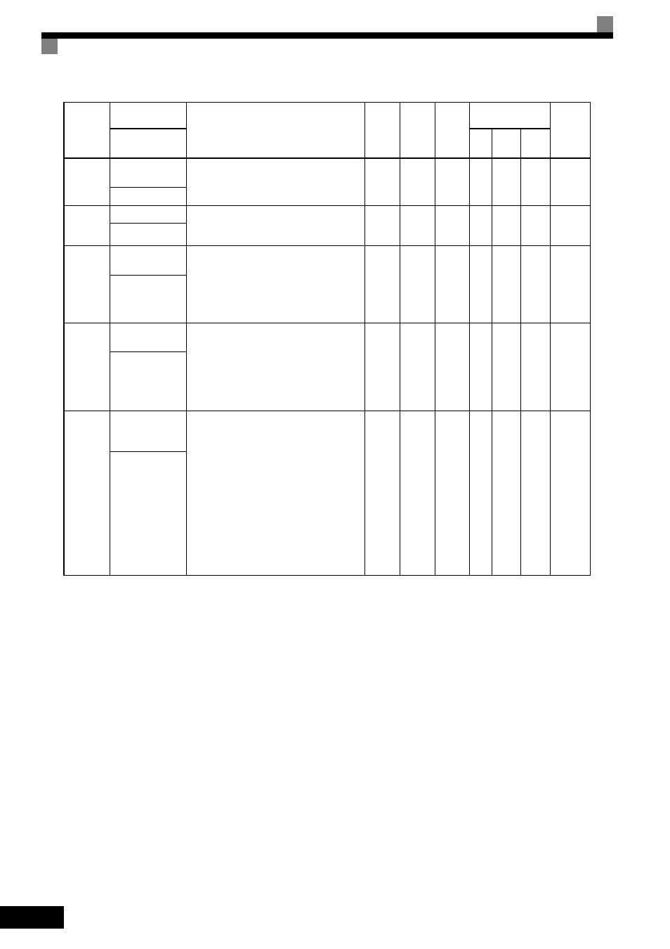
E2-11
Motor Rated
Output
Set the output of the motor in units of 0.01kW.
This parameter is automatically set during
Auto-Tuning.
5.50 to
650.00
5.50
*8
No
Q
Q
Q
318H
Mtr Rated Power
F1-01
PG Parameter
Set the number of pulses per rotation for the PG
(pulse generator or encoder) being used. (Do
not set as a multiple.)
0 to
60000
600
No
No
No
Q
380H
PG Pulses/Rev
H4-02
Terminal FM Gain
Setting
Set the voltage level gain for multi-function
analog output 1.
Set the number of multiples of 10 V to be out-
put as the 100% output for the monitor items.
Voltage output from the terminals, however,
have a 10 V max. meter calibration function.
*9
0.00 to
2.50
1.00
Yes
Q
Q
Q
41EH
Terminal FM Gain
H4-05
Terminal AM Gain
Setting
Set the voltage level gain for multi-function
analog output 2.
Set the number of multiples of 10 V to be out-
put as the 100% output for the monitor items.
Voltage output from the terminals, however,
have a 10 V max. A meter calibration function
is available.
*9
0.00 to
2.50
0.50
Yes
Q
Q
Q
421H
Terminal AM Gain
L1-01
Motor Overload
Protection
Selection
Set to enable or disable the motor overload pro-
tection function using the electronic thermal
relay.
0: Disabled
1: General-purpose motor protection
2: Inverter motor protection
3: Vector motor protection
In some applications when the MxC power
supply is turned off, the thermal value is
reset, so even if this parameter is set to 1,
protection may not be effective.
When several motors are connected to one
MxC, set to 0 and ensure that each motor is
installed with a protection device.
0 to 3
1
No
Q
Q
Q
480H
MOL Fault Select
Parameter
Number
Name
Description
Setting
Range
Default
Change
during
Run
Control
Methods
MEMO-
BUS
Register
Display
V/f
Open
Loop
Vector
Flux
Vector