Zero-servo function, Related parameters – Yaskawa Matrix Converter User Manual
Page 288
Individual Functions
6-
123
Zero-Servo Function
The Zero-Servo function holds the motor when the motor is stopped in what is call a Zero-Servo status. This
function can be used to stop the motor even with an external force acts on the motor or the analog reference
input is offset.
The Zero-Servo function is enabled when one of the multi-function inputs (H1-01 to H1-10) is set to 72 (Zero-
Servo Command). If the Zero-Servo Command is on when the frequency (speed) reference falls below the
Zero-Speed level, then the Zero-Servo function is triggered.
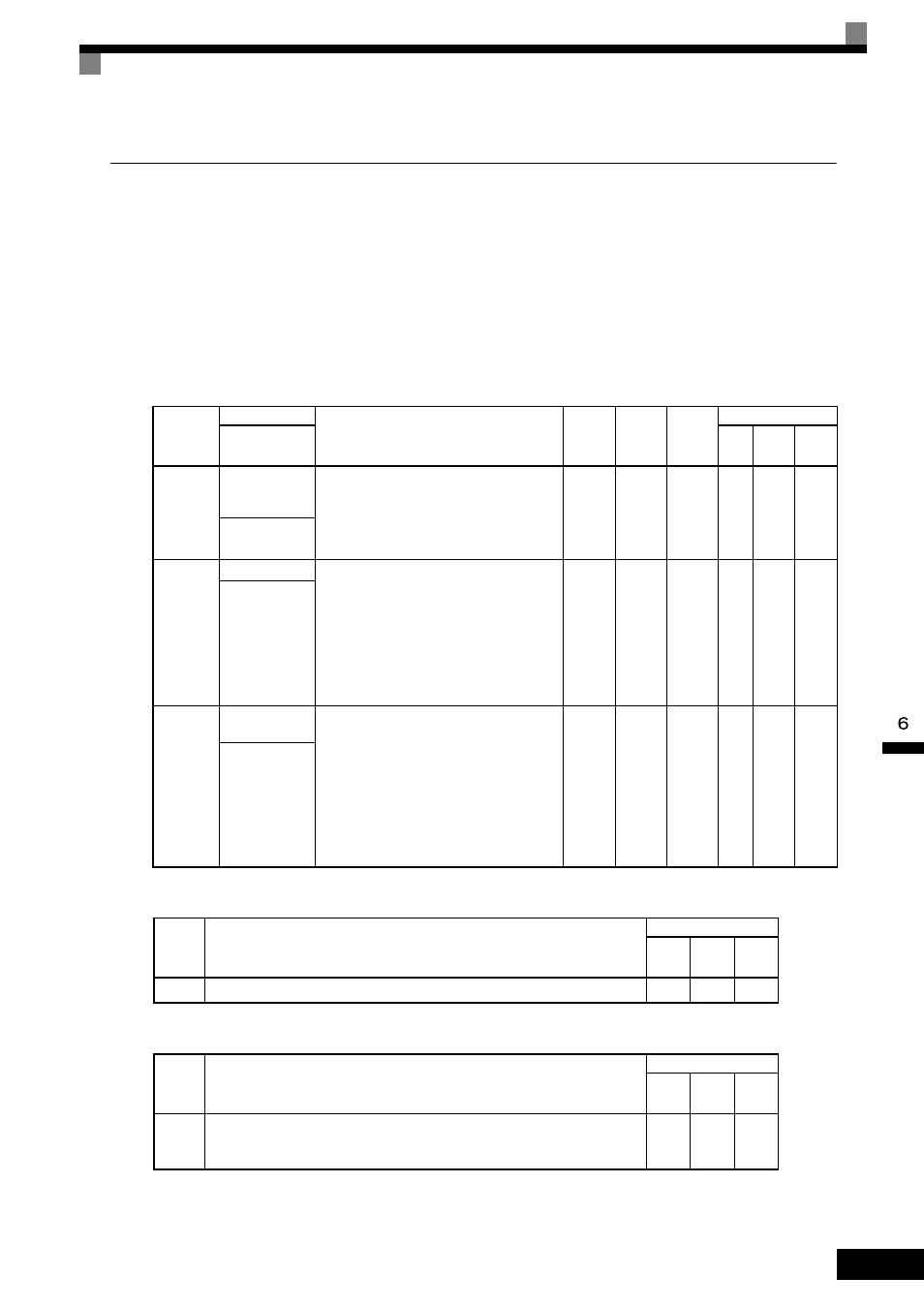
Related Parameters
Multi-function Digital Input Functions (H1-01 to H1-10)
Multi-Function Digital Output Functions (H2-01 to H2-03)
To output the Zero-Servo status externally, assign the Zero-Servo Complete signal (setting 33) to one of the
multi-function outputs (H2-01 to H2-03).
Parameter
Number
Name
Description
Setting
Range
Default
Change
during
Run
Control Methods
Display
V/f
Open
Loop
Vector
Flux
Vector
b2-01
DC Injection
Braking Start
Frequency
Sets the frequency at which DC injection brak-
ing starts when decelerate to stop (b1-03 = 0) is
selected. If b2-01< E1-09, DC Injection braking
starts at E1-09.
Note: Zero Speed restrictions are active in Flux
Vector Mode.
0.0 to
10.0
0.5 Hz
No
A
A
A
DCInj Start Freq
b9-01
Zero Servo Gain Adjust the strength of the zero-servo lock.
Enabled when the “zero-servo command” is set
for the multi-function input. When the zero-
servo command has been input and the fre-
quency reference drop below excitation level
(b2-01), a position control loop is created and
the motor stops. Increasing the zero-servo gain
in turn increases the strength of the lock.
Increasing it by too much will cause oscillation.
0 to 100
5%
No
No
No
A
Zero Servo Gain
b9-02
Zero Servo Com-
pletion Width
Sets the output width of the P-lock completion
signal.
Enabled when the “zero-servo completion
(end)” is set for a multi-function input. The
zero-servo completion signal is on when the
current position is within the range (the zero-
servo position
± zero-servo completion width.)
Set the allowable position displacement from
the zero-servo position to 4 times the pulse rate
of the PG (pulse generator, encoder) in use.
0 to
16383
10
No
No
No
A
Zero Servo
Count
Set
Value
Function
Control Methods
V/f
Open
Loop
Vector
Flux
Vector
72
Zero-Servo Command (ON: Zero-servo)
No
No
Yes
Set
Value
Function
Control Methods
V/f
Open
Loop
Vector
Flux
Vector
33
Zero-Servo Complete
ON: Current position is within zero-servo start position ± the Zero-Servo Complete
width.
No
No
Yes