Yaskawa Matrix Converter User Manual
Page 276
Individual Functions
6-
111
Application Precautions
If the analog signal input level is 0 to 10 V or 4 to 20 mA, a forward torque reference will not be applied. To
apply reverse torque, use an input level of -10 V to 10 V or switch the direction using a multi-function input
set to 78 (Polarity Reverse Command for external torque reference).
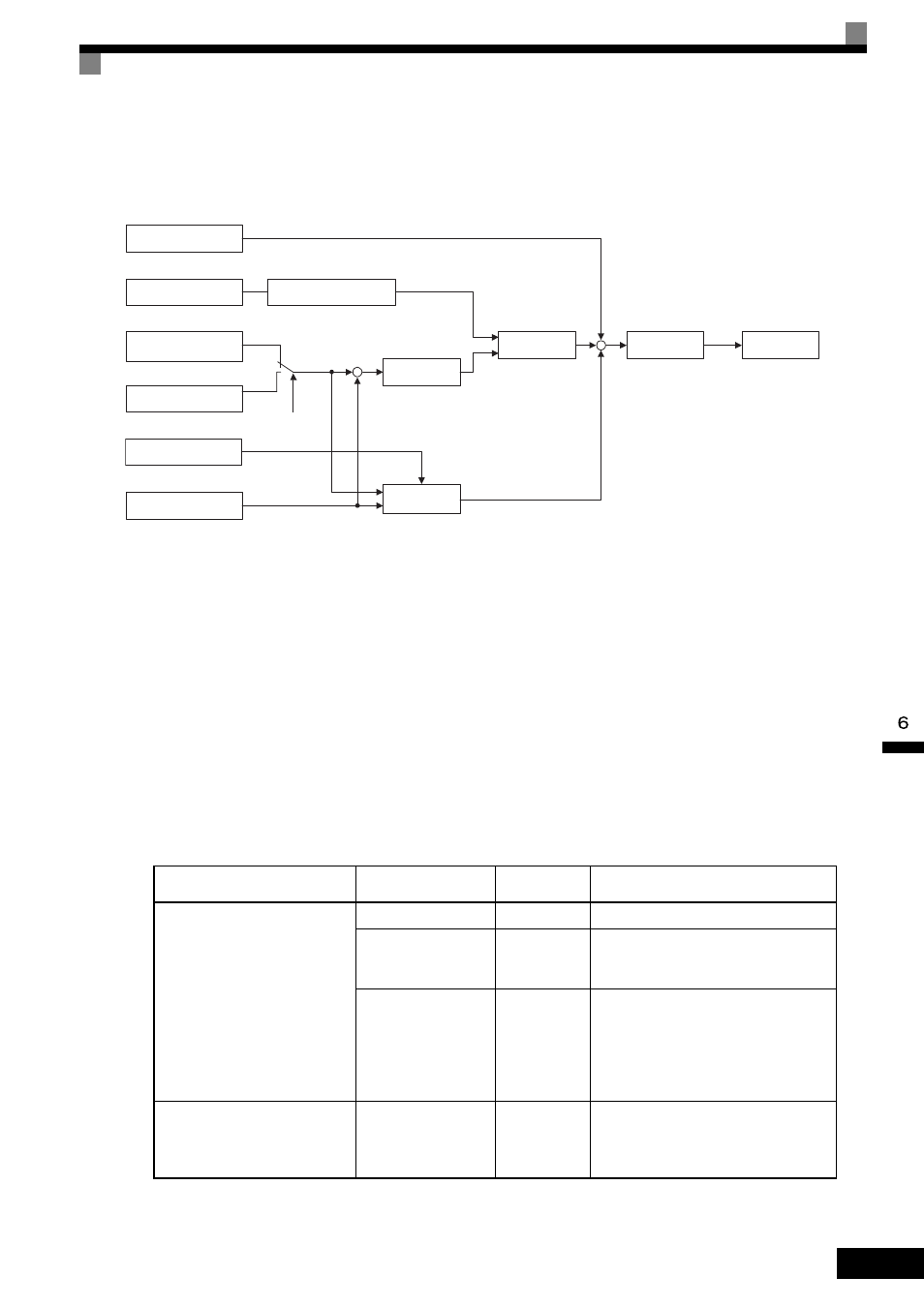
Fig 6.67 Torque Control Block Diagram
Speed Limiter and Priority Circuit (Speed Limit Function)
If the external torque reference and load are not balanced during torque control, the motor will accelerate in
either the forward or reverse direction. The speed limit function is used to limit the speed to a specified value
and it consists of the speed limiter circuit and priority circuit.
When the motor speed exceeds the speed limit value during torque control, the speed limiter circuit generates
the suppression torque proportional to the speed above the limit value and adds to the torque reference. The
priority circuit switches the internal torque reference to ASR output so that the motor speed does not exceed
the speed limit value.
Application Precautions
There are two ways to set a speed limit: using an input from an analog input terminal and setting a speed limit
in d5-04. The inputs methods for a speed limit are listed in the following table.
Speed Limit Input Method
Location of
Reference
Parameter
Settings
Remarks
Voltage input (0 to ±10 V)
Set in d5-04
d5-03 = 2
-
Between A1 and AC
b1-01 = 1
H3-01 = 1
Set H3-01 to 0 if the speed limit is always
to be positive.
Between A2 and AC
b1-01 = 0
H3-08 = 1
H3-09 = 1
The value will be added to the value input
on A1 to determine the speed limit.
Set H3-03 to 0 if the speed limit input on
A2 is always to be positive.
Turn off (V side) pin 2 of DIP switch S1
on the terminal board.
Current input (4 to 20 mA)
Between A2 and AC
b1-01 = 0
H3-08 = 2
H3-09 = 1
The value will be added to the value input
on A1 to determine the speed limit.
Turn on (I side) pin 2 of DIP switch S1 on
the terminal board.
Torque reference
from analog input
Torque Reference Delay
Time (d5-02)
Torque compensation
from analog input
Speed limit from analog
input from terminal A1
Speed Limit (d5-04)
1
2
d5-03
Speed limiter
Speed feedback
Speed Limit Bias (d5-05)
+
Torque limit
Internal torque
reference
Refer to torque limit setting
via constants and analog input
Speed controller
(ASR)
Priority
circuit
+
+
+
−