Yaskawa Matrix Converter User Manual
Page 158
5
-58
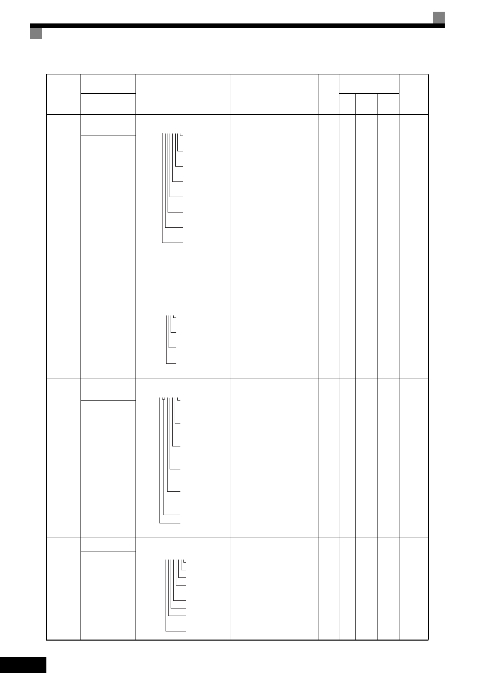
U1-10
Input terminal sta-
tus
Shows input on/off status.
The on/off status of the following
input terminals can be checked by
displaying U1-10 and pressing the
ENTER key. (Press the ENTER
key again to return to the original
display.) Upper 4 bits.
No output available
-
A
A
A
49H
Input Term Sts
U1-11
Output terminal
status
Shows output on/off status.
No output available
-
A
A
A
4AH
Output Term Sts
U1-12
Operation status
MxC operating status.
No output available
-
A
A
A
4BH
Int Ctl Sts 1
Parameter
Number
Name
Description
Output Signal Level
during Multi-Function
Analog Output
Min.
Unit
Control
Methods
MEMO-
BUS
Register
Display
V/f
Open
Loop
Vector
Flux
Vector
1: FWD command
(S1) is on.
1: REV command
(S2) is on.
1: Multi input 1
(S3) is on.
1: Multi input 2
(S4) is on.
1: Multi input 3
(S5) is on.
1: Multi input 4
(S6) is on.
1: Multi input 5
(S7) is on.
1:Multi input 6
(S8) is on.
U1-10= 00000000
1: Multi input 7
(S9) is on.
1: Multi input 8
(S10) is on.
1: Multi input 9
(S11) is on.
1: Multi input 10
(S12) is on.
U1-10= 0000
U1-11= 00000000
1: Multi-function
contact output
(M1-M2) is on.
1: Multi-funtion
contact output 1
(P1) is on.
1: Multi-funtion
contact output 2
(P2) is on.
1: Multi-function
contact output 3
(P3) is on.
1: Multi-function
contact output 4
(P4) is on.
Not used (always 0).
1: Error output
(MA/AB-MC) is on.
1: Run
1: Zero speed
1: Reverse
1: Reset signal
input
1: Speed agree
1: MxC ready
1: Minor fault
1: Major fault
U1-12= 00000000