Input p-con 1cn-41 – Yaskawa DR2 Sigma Servo User Manual
Page 108
3.2 Setting User Constants According to Host Controller
95
User constant Cn-03 can be used to change the voltage input range. (This is also applica-
ble to speed restriction.)
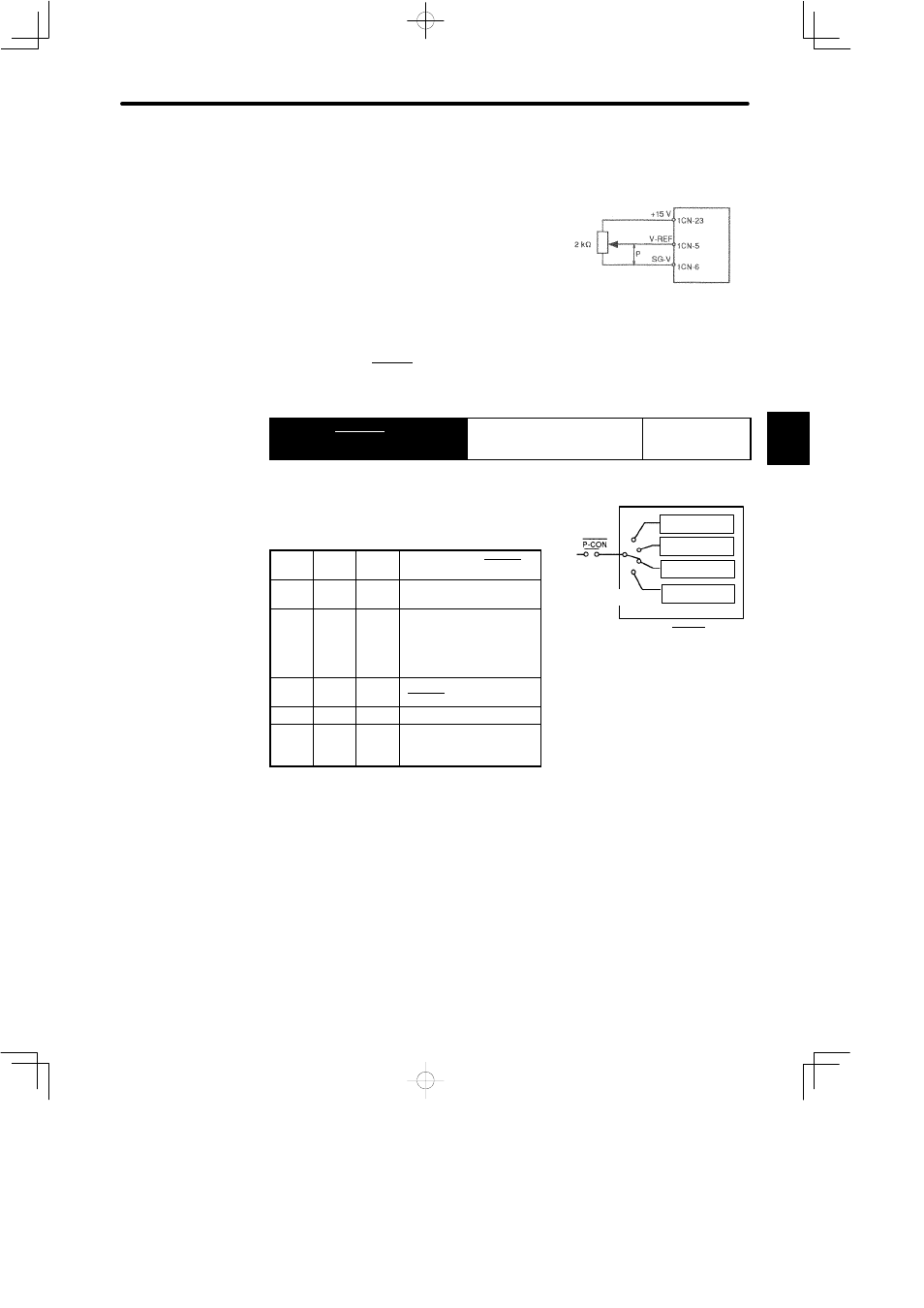
Example of Input Circuit:
See the figure on the right.
• For noise control, always use twisted-
pair cables.
• Example of Variable Resistor for Speed Setting:
Type 25HP-10B manufactured by Sakae Tsushin Kogyo Co., Ltd.
When input signal P-CON is used to switch between speed reference and torque refer-
ence for torque control II, set both bits A and B of memory switch Cn-01 to 1.
→ Input P-CON 1CN-41
Proportional Control, etc.
For Speed/Torque
Control and
Position Control
The function of this input signal varies according
to the memory switch setting.
Cn-02
Bit 2
Cn-01
Bit B
Cn-01
Bit A
Function of P-CON
0
0
0
Proportional control
(Standard setting)
0
0
1
Speed control with
zero-clamp function
Switching between
zero-clamp enabled/
prohibited mode
0
1
0
Torque control I
(P-CON is not used.)
0
1
1
Torque control II
1
−
−
Changing the direction of
rotation during contact
input speed control.
3
Servopack
Servopack
Proportional
control
Zero-clamp
control
Torque/speed
control
Rotation direction
control
Memory
switch
The function of P-CON signal
varies according to the memory
switch setting.