Yaskawa DR2 Sigma Servo User Manual
Page 468
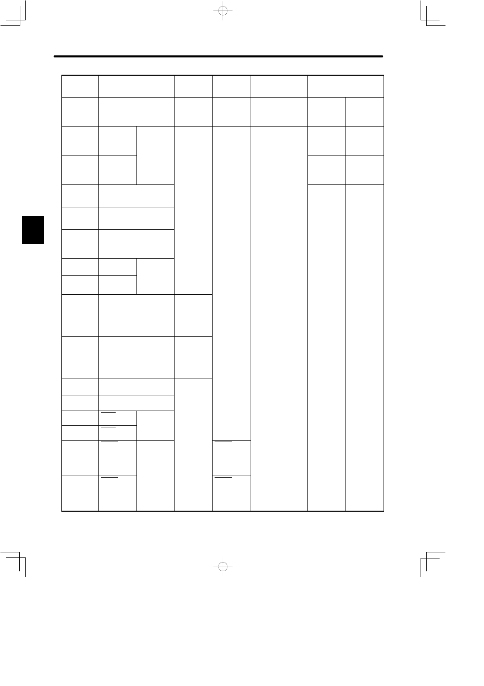
LIST OF I/O SIGNALS
458
Specifi-
cations
Contact Input Speed
Control
INHIBIT
Input
Brake
Interlock
Output
Absolute
Encoder
Standard Specifications
Memory
Switch
Setting
Cn-01 Bit F
= 1
Cn-02 Bit 2
= 1
Cn-01 Bit F
= 0
Cn-02 Bit 2
= 1
Cn-01 Bit F = 1
Cn-02 Bit 2 = 0
Cn-01
Bit E = 1
Cn-02
Bit 9 = 1
Standard Setting
(Cn-02 Bit B = 1)
14
*CLR
Clear input
3.2.2
−
(Unused)
3.2.6
CLR
Clear input
3.2.2
15
CLR
−
(Unused)
3.2.6
*CLR
Clear input
3.2.2
16
TRQ-M
Torque monitor
3.2.12
17
VTG-M
Speed monitor
3.2.12
18
PL3
Power for open collector
reference
3.2.2
19
PCO
PG signal
output
phase C
20
*PCO
phase-C
3.2.3
21
−
(Unused)
BAT+
Backup
battery +
input
3.8.5
22
−
(Unused)
BAT-
Backup
battery -
input
3.8.5
23
−
(Unused)
24
−
(Unused)
25
COIN+
Positioning
complete
26
COIN-
complete
signal
3.7.3
27
TGON+
TGON
output
signal
3 7 5
TGON+
Brake
interlock
signal
3.4.4
28
TGON-
3.7.5
TGON-
Brake
interlock
signal
3.4.4
C