Yaskawa DR2 Sigma Servo User Manual
Page 476
467
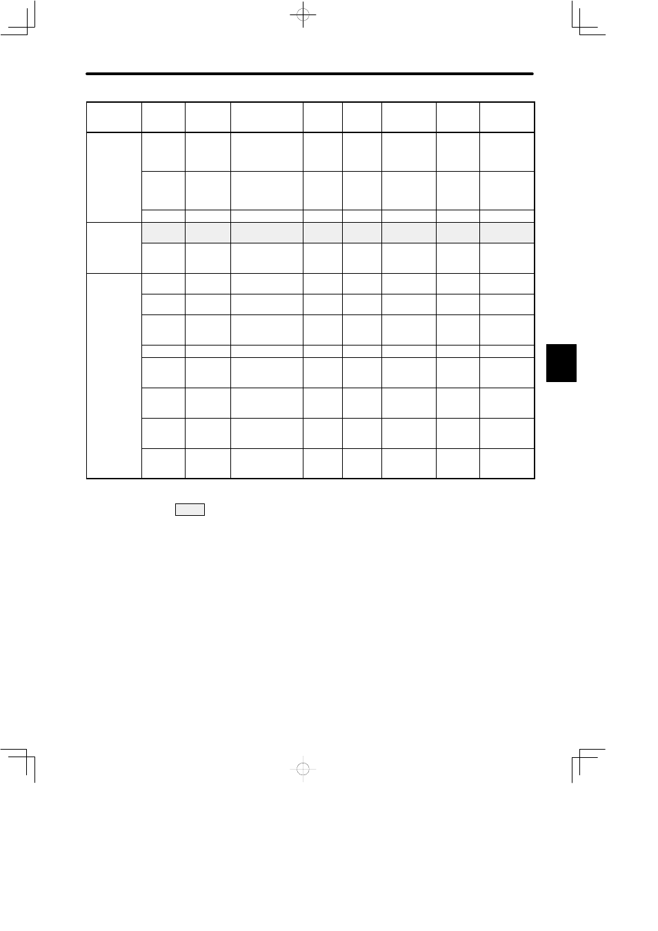
Category
Remarks
Factory
Setting
Upper
Limit
Lower
Limit
Unit
Name
Code
User
Constant
No.
Sequence
Related
Constants
Cn-16
BRKWAI
Output timing of
brake reference
during motor
operation
10 ms
10
100
50
See 3.4.4.
Cn-22
VCMPLV
Speed
coincidence
signal output
range
r/min
0
100
10
See 3.7.4.
Cn-29
ZCLVL
Zero-clamp level
r/min
0
4500
10
See 3.4.3.
Pulse
Related
Cn-0A
PGRAT
Dividing ratio
setting
P/R
16
32768
2048
See note 1
See 3.2.3.
e a ed
Constants
Cn-11
PULSNO
Number of
encoder pulses
P/R
513
32768
2048
See note 1
See 3.3.3,
3.8.5.
Other
Constants
Cn-0C
TRQMSW Mode switch
(torque reference)
%
0
800
200
See 3.6.6.
Co s a s
Cn-0D
REFMSW
Mode switch
(speed reference)
r/min
0
4500
0
See 3.6.6.
Cn-0E
ACCMSW Mode switch
(acceleration
reference)
10
(r/min)/s
0
3000
0
See 3.6.6.
Cn-10
JOGSPD
Jog speed
r/min
0
4500
500
See 3.3.2.
Cn-1F
SPEED1
1st speed
(contact input
speed control)
r/min
0
4500
100
See 3.2.6.
Cn-20
SPEED2
2nd speed
(contact input
speed control)
r/min
0
4500
200
See 3.2.6.
Cn-21
SPEED3
3rd speed
(contact input
speed control)
r/min
0
4500
300
See 3.2.6.
Cn-28
NFBCC
Speed loop
compensation
constant
---
0
100
0
: User constants that must be always set
Note
1) After changing the setting, always turn the power OFF, then ON. This makes the new
setting valid.
2) Automatically set by autotuning function
3) Valid only when zero-clamp function is used
4) To use soft start function, always set both Cn-07 and Cn-23.
D