Yaskawa DR2 Sigma Servo User Manual
Page 458
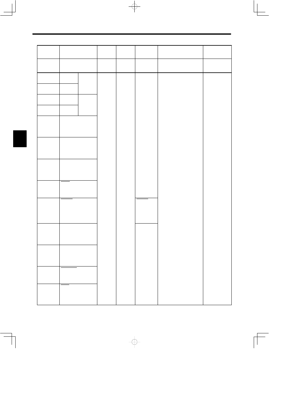
LIST OF I/O SIGNALS
448
Specifi-
cations
Torque
Control I
Speed Control with
Torque Feed Forward
Zero-
clamp
Speed
Coincide
Output
Absolute
Encoder
Standard
Specifications
Memory
Switch
Setting
Cn-01
Bit A = 0
Bit B = 1
Cn-01 Bit F = 1
Cn-01
Bit A = 1
Bit B = 0
Cn-01
Bit 4 = 1
Cn-01
Bit 9 = 1
Standard Setting
(Cn-02 BitB = 0)
Memory
Switch
Setting
Cn-01
Bit A = 0
Bit B = 1
Cn-01 Bit F = 1
Cn-01
Bit A = 1
Bit B = 0
Cn-01
Bit 4 = 1
Cn-01
Bit 9 = 1
Standard Setting
(Cn-02 BitB = 0)
33
PAO
PG signal
output
phase A
34
*PAO
phase-A
3.2.3
35
PBO
PG signal
output
phase B
36
*PBO
phase-B
3.2.3
37
ALO1
Alarm code output
(Open collector)
3.7.1
38
ALO2
Alarm code output
(Open collector)
3.7.1
39
ALO3
Alarm code output
(Open collector)
3.7.1
40
S-ON
Servo ON input
3.7.2
41
P-CON
P control input
3.6.4
P-CON
Zero-clamp
operation
reference
3.4.3
42
P-OT
Forward rotation
prohibited
3.1.2
43
N-OT
Reverse rotation
prohibited
3.1.2
44
ALM-RST
Alarm reset input
3.7.1
45
P-CL
Forward torque limit
ON input
3.1.3
C