Yaskawa DR2 Sigma Servo User Manual
Page 136
3.6 Minimizing Positioning Time
123
3) Servopacks can use four types of mode switches (1 to 4). To select a mode switch, use
the following memory switch. Note that the mode switch setting methods for speed/
torque control and position control are slightly different.
For Speed/
Torque
Control
For Position
Control
Memory
Switch
Cn-01
Memory
Switch Cn-01
Mode Switch Setting
User Constant
Unit
Bit D Bit C
Bit
D
Bit
C
Bit
B
1
1
−
−
1
Does not use mode
switch.
0
0
0
0
0
Uses torque reference as
a detection point.
(Standard setting)
Cn-0C
Percentage of
rated torque: %
0
1
0
1
0
Uses speed reference as
a detection point.
Cn-0D
Motor speed:
r/min
1
0
1
0
0
Uses acceleration refer-
ence as a detection point. Cn-0E
Acceleration
reference in-
side the Servo-
pack:
10 (r/min)/s
1
1
0
Uses error pulse as a
detection point.
Cn-0F
Reference unit
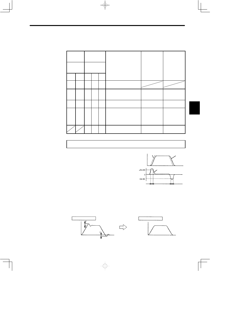
When Torque Reference Is Used as a Detection Point of
Mode Switch
(Standard
Setting)
If a torque reference exceeds the torque value set
in user constant Cn-0C, the speed loop switches
to P control.
The DR2 Servopack is factory set to this standard
mode (Cn-0C = 200).
Example of Use:
If a mode switch is not used and PI control is always performed, torque may
enter a saturation state during acceleration or deceleration, causing the motor
speed to have overshoot or undershoot.
Using the mode switch suppresses torque saturation and prevents the motor
speed from having overshoot and undershoot.
Without mode switch
Overshoot
Motor
speed
Undershoot
Time
With mode switch
Motor
speed
Time
3
Speed
Reference
speed
Motor
speed
Internal torque
reference
Torque
PI control
P control
PI control
PI control
P control