Yaskawa DR2 Sigma Servo User Manual
Page 462
LIST OF I/O SIGNALS
452
Specifi-
cations
Speed Control
with Torque Limit
by Analog
Voltage
Reference
Contact Input Speed Control
Brake
Interlock
Output
Standard Specifications
Memory
Switch
Setting
Cn-02
Bit F = 1
Cn-02 Bit 2 = 1
Cn-01 Bit E
Standard Setting
(Cn-02 bitB = 0)
Memory
Switch
Setting
Cn-02
Bit F = 1
Cn-01
Bit B = 1
Cn-01
Bit B = 0
Cn-01 Bit E
Standard Setting
(Cn-02 bitB = 0)
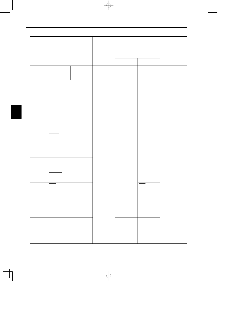
35
PBO
PG signal
output
36
*PBO
output
phase-B
3.2.3
37
ALO1
Alarm code output
(Open collector)
3.7.1
38
ALO2
Alarm code output
(Open collector)
3.7.1
39
ALO3
Alarm code output
(Open collector)
3.7.1
40
S-ON
Servo on input
3.7.2
41
P-CON
P control input
3.6.4
42
P-OT
Forward rotation prohibited
3.1.2
43
N-OT
Reverse rotation prohibited
3.1.2
44
ALM-RST
Alarm reset input
3.7.1
45
P-CL
Forward torque limit ON input
3.1.3
P-CL
Contact input
speed control
1
3.2.6
46
N-CL
Reverse torque limit ON input
3.1.3
N-CL
Contact input
speed control
2
3.2.6
N-CL
Contact input
speed control
2
3.2.6
47
+24VIN
I/O power supply
3.2.4
48
−
(Unused)
49
−
(Unused)
C