Yaskawa DR2 Sigma Servo User Manual
Page 98
3.2 Setting User Constants According to Host Controller
85
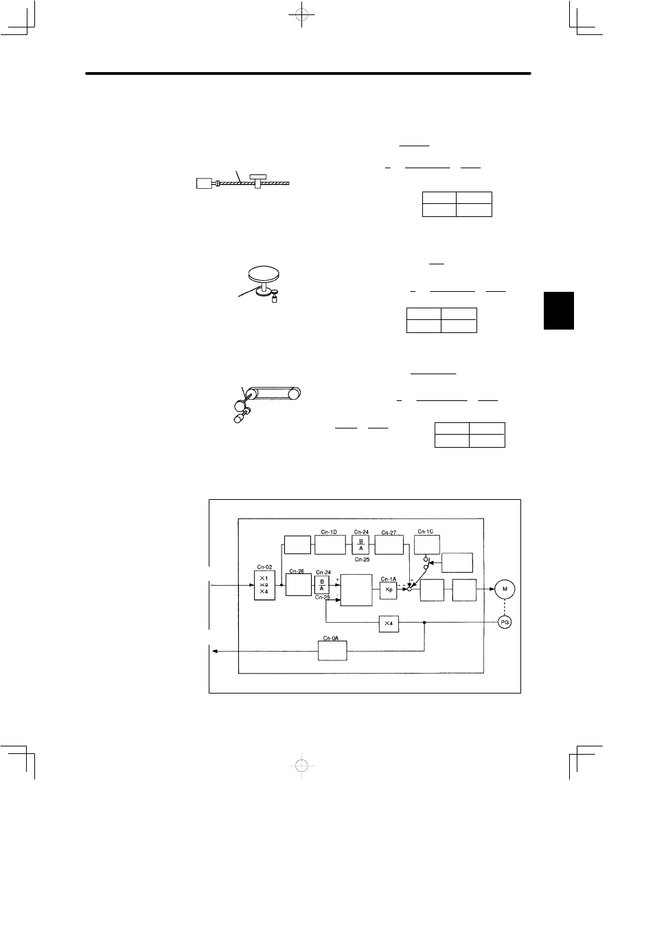
3) Examples of Setting an Electronic Gear Ratio for Different Load Mechanisms
Ball Screw
Reference unit: 0.001 mm
Load shaft
Incremental
encoder:
Ball screw
pitch: 6 mm
Travel distance per
revolution of load shaft
Electronic gear ratio
Preset
values
Cn-24
Cn-25
B
A
=
2048 × 4 × 1
6000 × 1 =
Cn-24
Cn-25
=
6mm
0.001mm =
6000
8192
6000
2048 pulses per revolution
Disc Table
Reference unit:
0.1°
Gear ratio:
3 : 1
Load shaft
Incremental encoder:
2048 pulses per revolution
Travel distance per
revolution of load shaft
Preset
values
24576
3600
Cn-24
Cn-25
0.1°
360°
=
= 3600
Electronic gear ratio
B
A
=
2048 × 4 × 3
3600 × 1 =
Cn-24
Cn-25
Belt & Pulley
Pulley diameter:
100 mm
Absolute encoder:
1024 pulses per revolution
Cn-24
Cn-25
Load shaft
Reference unit: 0.0254 mm
Gear ratio:
2.4 : 1
Travel distance per
revolution of load shaft =
3.14 x 100mm
0.0254mm =
12362
Electronic gear ratio
B
A
=
1024 × 4 × 2.4
12362 × 1
=
Cn-24
Cn-25
49152
61810
=
9830.4
12362 =
49152
61810
Preset
values
4) Control Block Diagram for Servopack for Position Control
DR2 Servopack for position control
Feed-forw
ard gain
Primary
lag filter
Bias
COIN
signal
Speed
loop
Current
loop
SGM
Servomotor
Encoder
Error
counter
Frequency
dividing
Differ-
entiation
Reference
pulse
PG signal
output
Smooth−
ing
3