Yaskawa DR2 Sigma Servo User Manual
Page 307
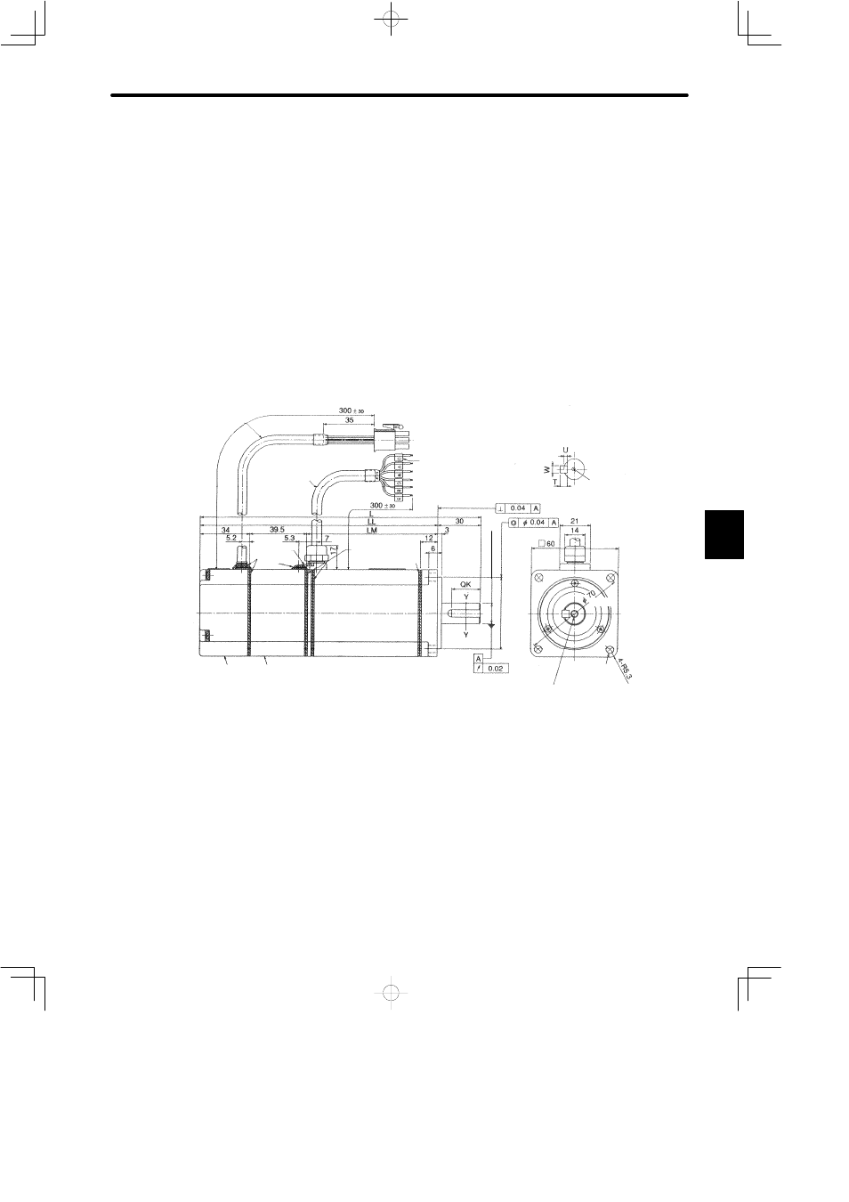
5.4 Σ-Series Dimensional Drawings
295
Note
1) The detector uses an incremental encoder 2048 P/R.
2) Type “V” indicates 200 V specification, and type “W” indicates 100 V specification.
3) “A3V(W)314B”, “A3V(W)316B”, “A5V(W)314B”, “A5V(W)316B”, “01V(W)314B” and
“01V(W)316B” have a keyed shaft. The keyway complies with JIS B 1301-1976 (preci-
sion). A straight key is supplied.
4) The quoted allowable radial load is the value at a position 20 mm (0.79 in.) from the mo-
tor mounting surface.
5) The electromagnetic brake is only to hold the load in position and cannot be used to stop
the motor.
• 200 W (0.53 HP), 300 W (0.40 HP), 400 W (0.27 HP)
Encoder Lead
UL2854
Incremental Encoder
2048 P/R
Cross-section Y-Y
(0.20)
4-φ5.5 (φ0.22)
MTG Holes
Motor Lead φ7
(φ0.29)
Sealant
(0.0016)
(φ0.0008)
(1.34)
(0.83)
(11.81¦1.18)
(1.38)
(0.12)
(1.18)
(11.81¦1.18)
φ
50
0 -0.025
1.97
-0.0010
0
φ
(
)
(0.28)
(0.24)
(φ2.76)
(2.36)
(φ0.55)
(1.56)
Shaft end screw hole
(SGM-jjV(W)316B,
with key type only)
Marked Wire
Sealant
φ
14
0 -0.01
1
φ
0.55
-0.0004
0
(
)
(φ0.0016)
Brake Lead
Sealant
(0.21)
Holding Brake
(Deenergisation Operation)
Voltage: 90VDC, Dissipated
Current (Reference): 0.08A
Brake Holding Torque = Motor
Rated Torque
(0.47)
Screw
5