Yaskawa DR2 Sigma Servo User Manual
Page 230
SERVO SELECTION AND DATA SHEETS
5.2.1 Ratings and Specifications cont.
218
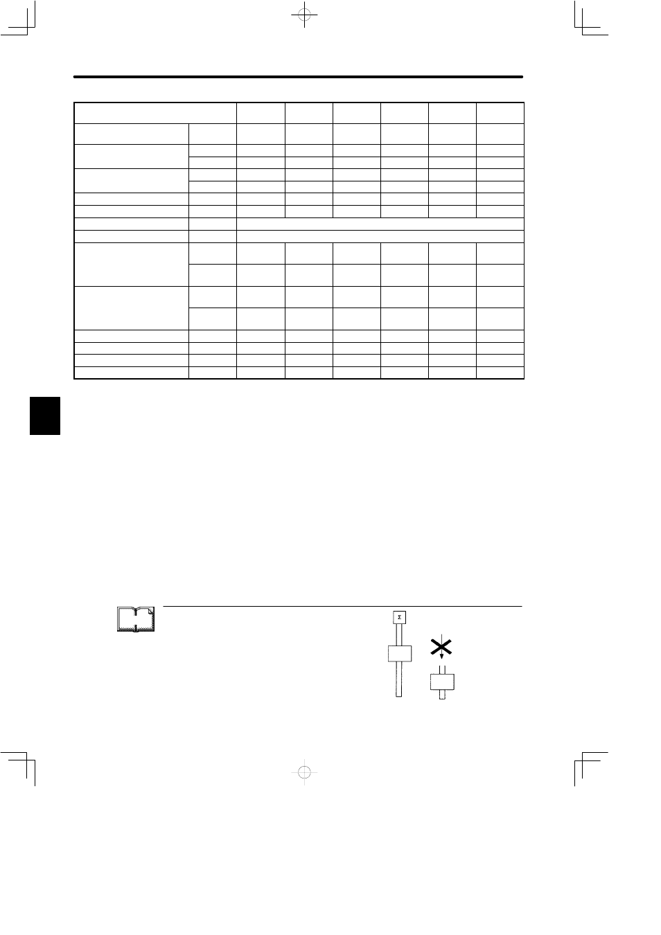
SGM Servomotor
A3A
A3V
A5A
A5V
01A
01V
02A
02V
04A
04V
08A
08V
Rated Output*
1
W (HP)
30
(0.04)
50
(0.07)
100
(0.13)
200
(0.27)
400
(0.53)
750
(1.01)
Rated Torque*
1
*
2
N¡m
0.095
0.159
0.318
0.637
1.27
2.39
q
(oz¡in)
(13.5)
(22.6)
(45.1)
(90.1)
(181)
(338)
Instantaneous Peak Torque*
1
N¡m
0.29
0.48
0.96
1.91
3.82
7.1
q
(oz¡in)
(40.5)
(67.7)
(135)
(270)
(542)
(1010)
Rated Curent*
1
A (rms)
0.42
0.6
0.87
2.0
2.6
4.4
Instantaneous Max Current*
1
A (rms)
1.3
1.9
2.8
6.0
8.0
13.9
Rated Speed*
1
r/min
3000
Instantaneous Max Speed*
1
r/min
4500
Torque Constant*
1
N¡m/A
(rms)
0.255
0.286
0.408
0.355
0.533
0.590
(oz¡in/A)
(rms)
(36.2)
(40.5)
(57.8)
(50.2)
(75.5)
(83.5)
Moment of Inertia [J
M
]
kg¡m
2
¢
10
−4
0.021
0.026
0.040
0.123
0.191
0.671
(oz¡in¡s
2
¢
10
−3
)
(0.288)
(0.368)
(0.576)
(1.74)
(2.70)
(9.52)
Rated Power Rate*
1
kW/s
4.36
9.63
25.4
32.8
84.6
85.1
Rated Angular Acceleration*
1
rad/s
2
45200
61200
79500
51800
666000
35600
Inertia Time Constant
ms
1.5
0.9
0.5
0.4
0.3
0.3
Inductive Time Constant
ms
1.5
1.8
1.9
5.4
6.4
13
*
1
These items and torque-motor speed characteristics quoted in combination with a DR2
Servopack at an armature winding temperature of 100°C. Other values quoted at 20°C. All
values typical at power voltage 200V.
*
2
Rated torques are continuous allowable torque values at 40°C with a 250 x 250 x 6 (mm)
(9.84 x 9.84 x 0.24 (in.)) heat sink attached.
NOTE
The ratings and specifications above refer to a standard Servomotor.
Add the numerical values below to the moment of inertia values in the table for a motor
fitted with a holding brake and/or a 12-bit absolute encoder.
Other specifications will also change slightly.
TERMS
Holding Brake
The holding brake is automatically applied to the
motor shaft to prevent the load falling in vertical axis
applications when the motor power supply is turned
off or fails. It is only to hold the load and cannot be
used for stopping motor.
Motor
Load
Prevent load falling
Load
5