For position control – Yaskawa DR2 Sigma Servo User Manual
Page 480
471
For Position Control
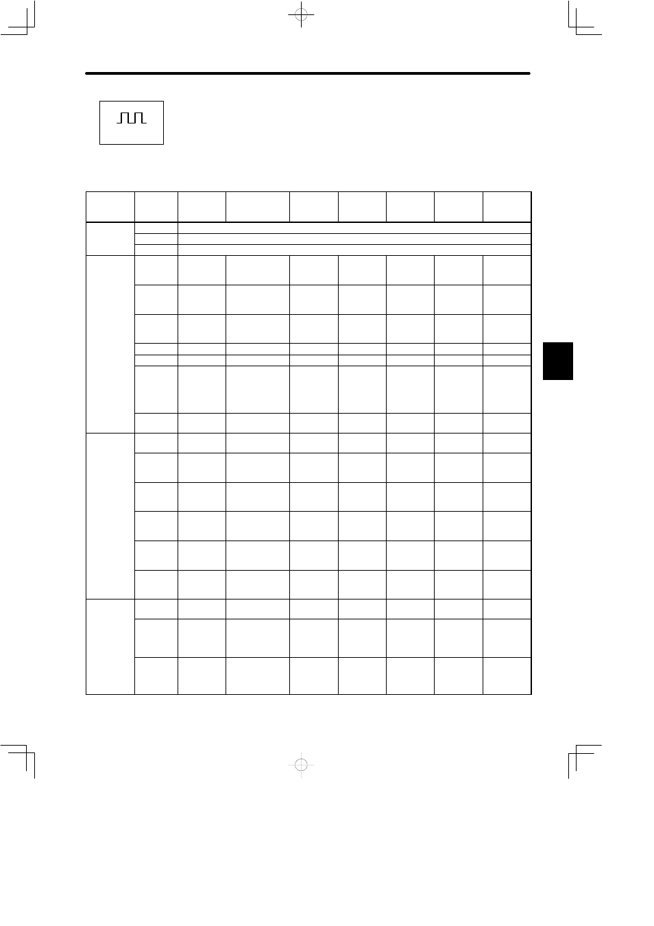
List of User Constants (User Constant Setting)
Category
User
Constant
No.
Code
Name
Unit
Lower
Limit
Upper
Limit
Factory
Setting
Remarks
Cn-00
Not a user constant. (Cn-00 is used to select special mode for digital operator.)
See 4.1.3.
Cn-01
Memory switch (see on page 474.)
See note 1
Cn-02
Memory switch (see on page 476.)
See note 1
Gain
Related
Constants
Cn-04
LOOPHS
Speed loop
gain
Hz
1
2000
80
See note 2
See 3.6.1,
3.6.2.
Cn-05
PITIME
Speed loop
integration time
constant
0.01ms
2
10000
2000
See note 2
See 3.6.1,
3.6.2.
Cn-1A
POSGN
Position loop
gain
1/s
1
500
40
See note 2
See 3.6.1,
3.6.2.
Cn-1C
BIASLV
Bias
r/min
0
450
0
See 3.6.5.
Cn-1D
FFGN
Feed-forward
%
0
100
0
See 3.6.3.
Cn-26
ACCTME
Position
reference
acceleration/de
celeration time
constant
100 µs
0
640
0
See 3.5.2.
Cn-27
FFFILT
Feed-forward
reference filter
100 µs
0
640
0
See 3.6.3.
Torque
Related
Cn-06
EMGTRQ
Emergency
stop torque
%
0
Max.
torque
Max.
torque
See 3.1.2.
e a ed
Constants
Cn-08
TLMTF
Forward
rotation torque
limit
%
0
Max.
torque
Max.
torque
See 3.1.3.
Cn-09
TLMTR
Reverse
rotation torque
limit
%
0
Max.
torque
Max.
torque
See 3.1.3.
Cn-17
TRQFIL
Torque
reference filter
time constant
100 µs
0
250
4
See 3.5.5.
Cn-18
CLMIF
Forward
external torque
limit
%
0
Max.
torque
100
See 3.1.3.
Cn-19
CLMIR
Reverse
external torque
limit
%
0
Max.
torque
100
See 3.1.3.
Sequence
Related
Cn-0B
TGONLV
Zero-speed
level
r/min
1
4500
20
See 3.7.5.
e a ed
Constants
Cn-12
BRKTIM
Time delay
from brake
reference until
servo OFF
10 ms
0
50
0
See 3.4.4.
Cn-15
BRKSPD
Speed level for
brake reference
output during
motor operation
r/min
0
4500
100
See 3.4.4.
D
Positions