Yaskawa DR2 Sigma Servo User Manual
Page 168
3.8 Special Wiring
155
b) Contents of Absolute Data
Serial Data:
Indicates how many turns the motor shaft has made from
the reference position (position specified at setup).
Initial Incremental Pulse:
Outputs pulses at the same pulse rate as when the motor
shaft rotates from the home position to the current posi-
tion at the maximum speed of 4900 r/min.
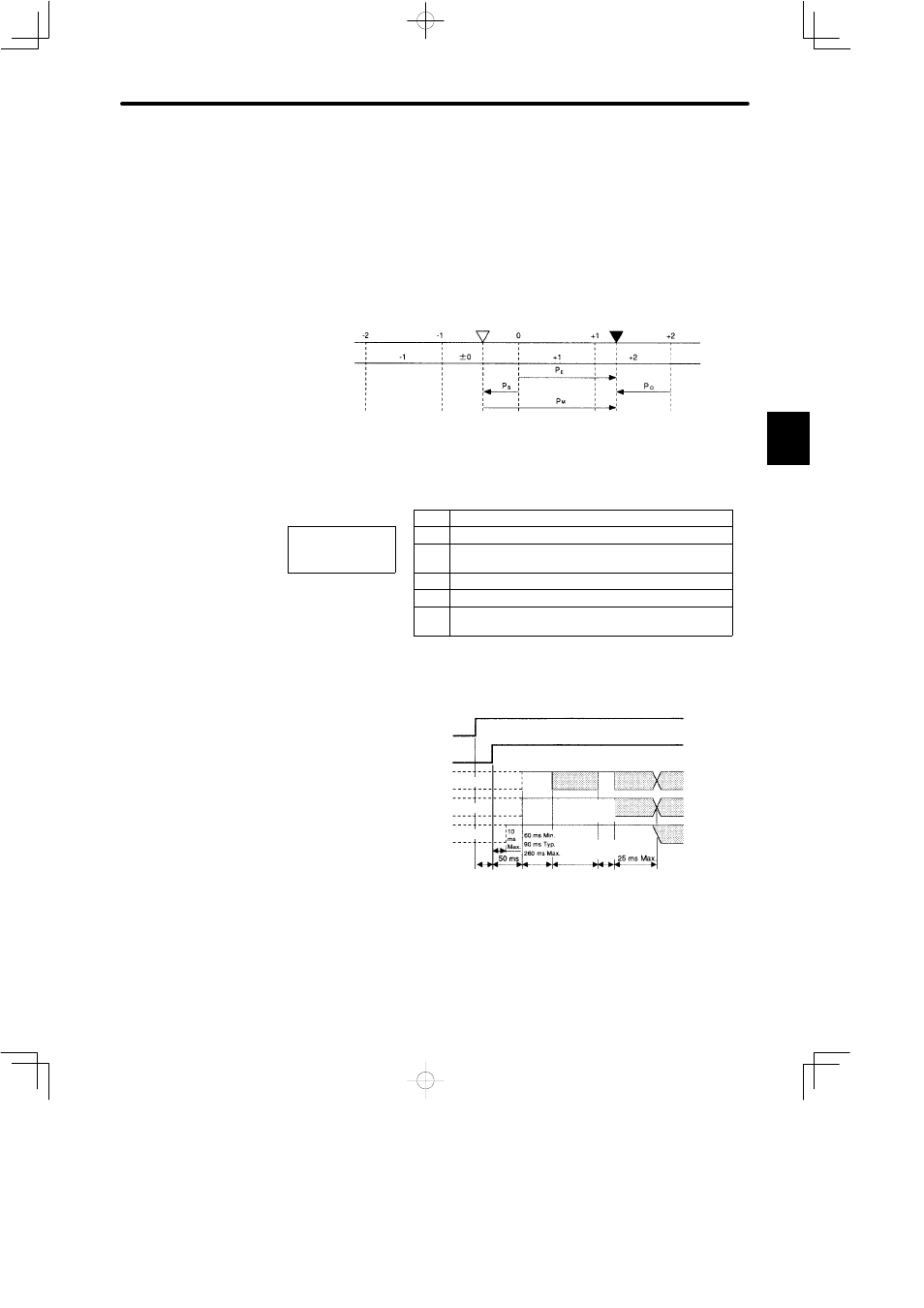
Coordinate data
Reference position
(setup)
Current position
Value M
Absolute data P
M
can be determined using the following formula.
P
E
Current value read by encoder
P
E
= M ¢ R+P
O
M
Serial data (rotation count data)
P
E
= M ¢ R+P
O
P
M
= P
E
− P
S
P
O
Number of initial incremental pulses
(Normally, this is a negative value)
P
S
Number of initial incremental pulses read at setup
P
M
Current value required for the customer system
R
Number of pulses per encoder revolution
(pulse count after dividing, value of Cn-0A)
c) Absolute Data Transmitting Sequence
(1) Set the SEN signal at
high level.
(2) After 100 ms, set the
system to serial data
reception-waiting-state.
Clear the incremental
pulse up/down counter
to zero.
(3) Receive eight bytes of
serial data.
(4) The system enters a
normal incremental op-
eration state approximately 50 ms after the last serial data is received.
3
Undefined
Rotation count
serial data
Initial incremental
pulse
Incremental
pulse
(Phase A)
(Phase A)
(Phase B)
(Phase B)
Incremental
pulse
Rotation count
serial data
Undefined
Undefined
Initial
incremental
pulse
1 to
3 ms
10 to
15 ms
Approx.
23 ms