Yaskawa DR2 Sigma Servo User Manual
Page 469
459
Specifi-
cations
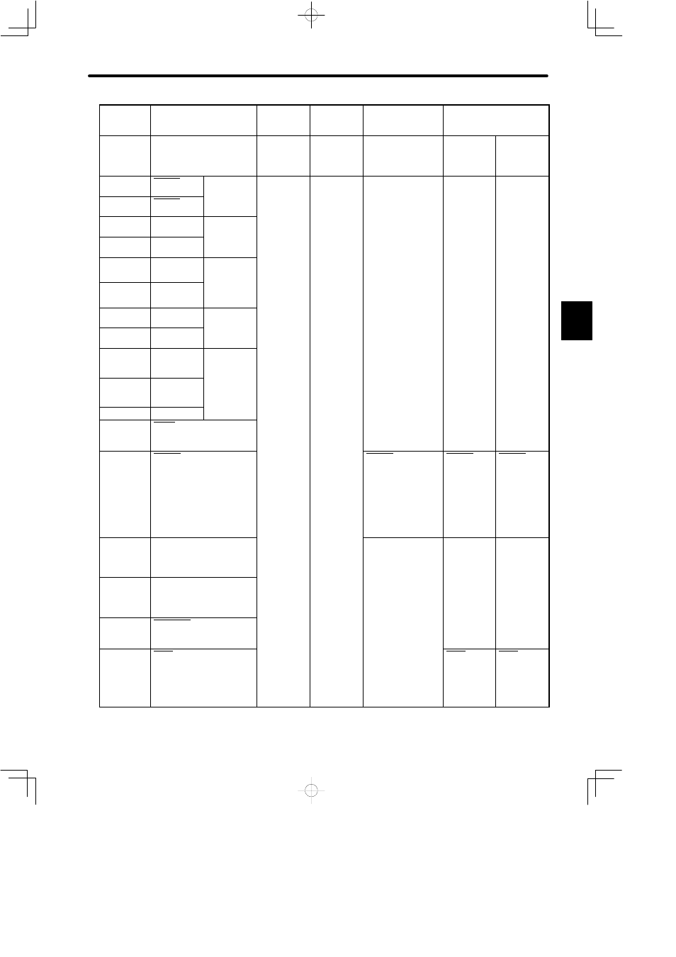
Contact Input Speed
Control
INHIBIT
Input
Brake
Interlock
Output
Absolute
Encoder
Standard Specifications
Memory
Switch
Setting
Cn-01 Bit F
= 1
Cn-02 Bit 2
= 1
Cn-01 Bit F
= 0
Cn-02 Bit 2
= 1
Cn-01 Bit F = 1
Cn-02 Bit 2 = 0
Cn-01
Bit E = 1
Cn-02
Bit 9 = 1
Standard Setting
(Cn-02 Bit B = 1)
29
S-RDY+
Servo ready
output
30
S-RDY-
output
3.7.6
31
ALM+
Servo alarm
output
32
ALM-
output
3.7.1
33
PAO
PG signal
output
phase A
34
*PAO
phase-A
3.2.3
35
PBO
PG signal
output
36
*PBO
output
phase-B
3.2.3
37
ALO1
Alarm code
output
(Open
38
ALO2
(Open
collector)
3.7.1
39
ALO3
40
S-ON
Servo ON input
3.7.2
41
P-CON
P control input
3.6.4
P-CON
INHIBIT input
3.2.10
P-CON
Rotation
direction
reference at
contact
input speed
control
3.2.6
P-CON
Rotation
direction
reference at
contact
input speed
control
3.2.6
42
P-OT
Forward rotation
prohibited
3.1.2
43
N-OT
Reverse rotation
prohibited
3.1.2
44
ALM-RST
Alarm reset input
3.7.1
45
P-CL
Forward torque limit ON
input
3.1.3
P-CL
Contact
input speed
control 1
3.2.6
P-CL
Contact
input speed
control 1
3.2.6
C