4 using speed coincidence output signal – Yaskawa DR2 Sigma Servo User Manual
Page 147
APPLICATIONS OF Σ-SERIES PRODUCTS
3.7.4 Using Speed Coincidence Output Signal
134
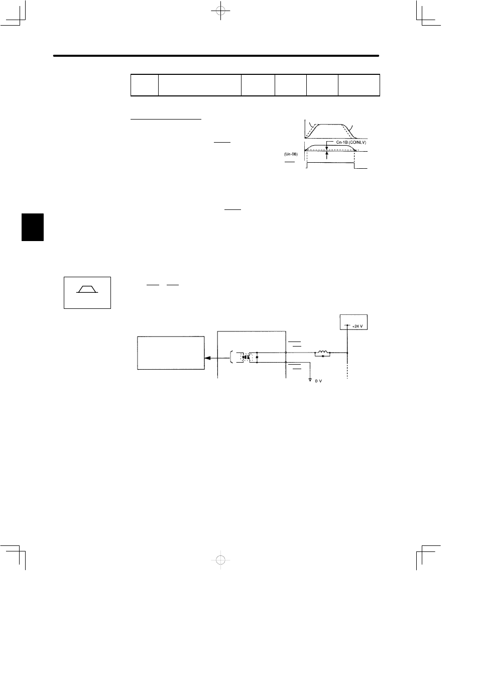
Cn-1B
COINLV
Positioning
Complete
Range
Unit:
Reference
Unit
Setting
Range: 0
to 250
Factory
Setting: 7
For Position
Control Only
For position control only.
This user constant is used to set output timing of
positioning complete signal (COIN+, 1CN-25) to
be output when motor operation is complete after
a position reference pulse has been input.
Set the number of error pulses in terms of reference unit (the number of input pulses that
is defined using the electronic gear function).
If too large a value is set in this user constant, error may become too small when the mo-
tor runs at a low speed, causing COIN+ to be output continuously.
COINLV does not affect the final positioning accuracy.
3.7.4 Using Speed Coincidence Output Signal
1) This section describes how to wire and use contact output signal “speed coincidence out-
puts (LCT+, CLT-).” This signal is output to indicate that actual motor speed matches a
reference speed. The host controller uses this signal as an interlock.
Photocoupler Output
Per output:
Maximum operation
voltage: 30 VDC
Maximum output
current: 50 mADC
Servopack
I/O power
supply
1CN-25
1CN-26
V-CMP+
or CLT+
V-CMP-
or CLT-
3
Speed
Reference
Motor
Error pulse
COIN+
(1CN-25)
Speed/Torque