Dr2 servopack – Yaskawa DR2 Sigma Servo User Manual
Page 425
6.2 Troubleshooting
413
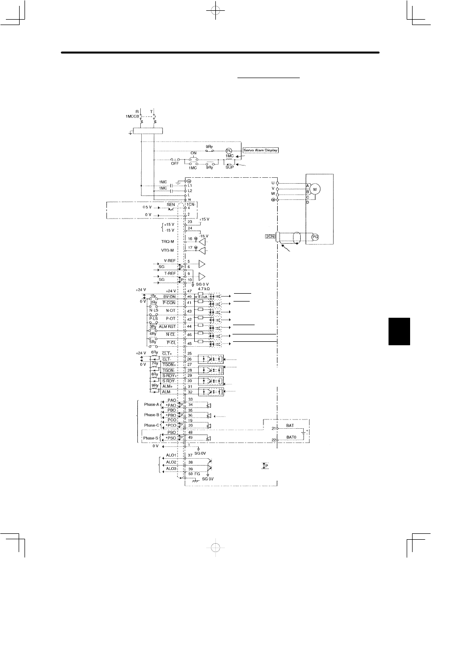
2) Instrument Connection Examples − Speed/Torque Control
Single-phase 200 to 230VAC
%, 50/60Hz
+10
-15
Noise Filter
Power Supply
SEN Signal Input
Power for Speed/Torque Reference
Max. Output Current: 30mADC
For Power Supply Switching
Attach surge suppressor to megnetic contactor and relays.
Torque Monitor: 3V/100%
Speed Monitor: 2V/1000r/min
Servomotor
Encoder
Correctly terminate end of
shielded cable.
Speed Reference Input
Rated Speed/¦2V to ¦10V
Torque Reference Input
Rated Torque/¦1V to ¦10V
Servo ON at 1Ry ON
P Control at 2Ry ON
Reverse Drive Disabled at N-LS OPEN
Forward Drive Disabled at P-LS OPEN
Alarm Reset at 3Ry ON
Reverse Torque Limit ON at 4Ry ON
Forward Torque Limit ON at 5Ry ON
6Ry ON for Torque Limit Detection
7Ry ON for TGON
8Ry ON for Servo Ready
9Ry OFF for Servo Alarm
PG Output
Line Driver
Alarm Code Output
DR2 Servopack
Servo ON
P Control
Reverse Drive Disabled
Forward Drive Disabled
Alarm Reset
Reverse Torque Limit ON
Forward Torque Limit ON
Torque Limit Detection
TGON
(ON when the motor zero-
speed level (set in the user
constant) is exceeded.)
Servo Ready
Servo Alarm
Line Driver
(Made by T-I)
Photocoupler Output
Maximum operational voltage: 30VDC
Maximum operational current: 50mA
When absolute encoder is used
Notes:
1. The capacity of each output circuit is below
30VDC, 50mA.
For 100VAC Application
Single-phase 100 to 115VAC
%, 50/60Hz
+10
-15
When absolute encoder is used
2.
: Twisted pair wires
3. I/O power supply must be prepared by customers.
6