5 control i/o – Yaskawa DR2 Sigma Servo User Manual
Page 432
MEASURES TO SATISFY THE REQUIREMENTS OF EMC DIRECTIVE
7.2.6 Digital Operator and Monitoring by Personal Computer
420
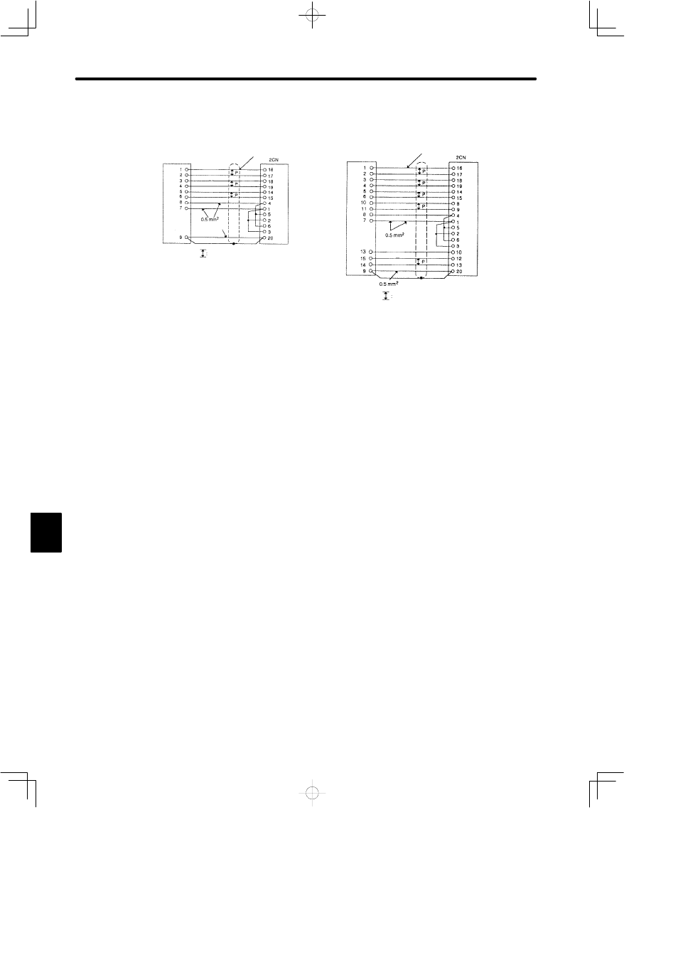
2) Connect the PG cable as follows:
S
Incremental Encoder
Incremental
Encoder
S
Absolute Encoder
Absolute
Encoder
Twisted−pair wires
Twisted−pair wires
Blue
White/Blue
White/Yellow
White/Green
Yellow
Green
Red
Black
Green/Yellow
Blue
White/Blue
White/Yellow
White/Green
Yellow
Green
Red
Black
Green/Blue
0.2mm
2
0.2mm
2
Purple
White/Purple
White/Grey
Orange
White/Orange
7.2.5 Control I/O
1) For control I/O (1CN) connector, use the following connector. Connector case shown
below is plated.
For 1CN cable, use the shielded cable and make sure to ground between cable shield
and connector case.
Also, perform shield processing on host controller side securely.
Connector: MR−50M
Connector Case: MR−50L4
7.2.6 Digital Operator and Monitoring by Personal Computer
1) Use digital operator or personal computer (for monitoring) only at test run.
Disconnect them during normal operation.
7