Yaskawa DR2 Sigma Servo User Manual
Page 84
3.2 Setting User Constants According to Host Controller
71
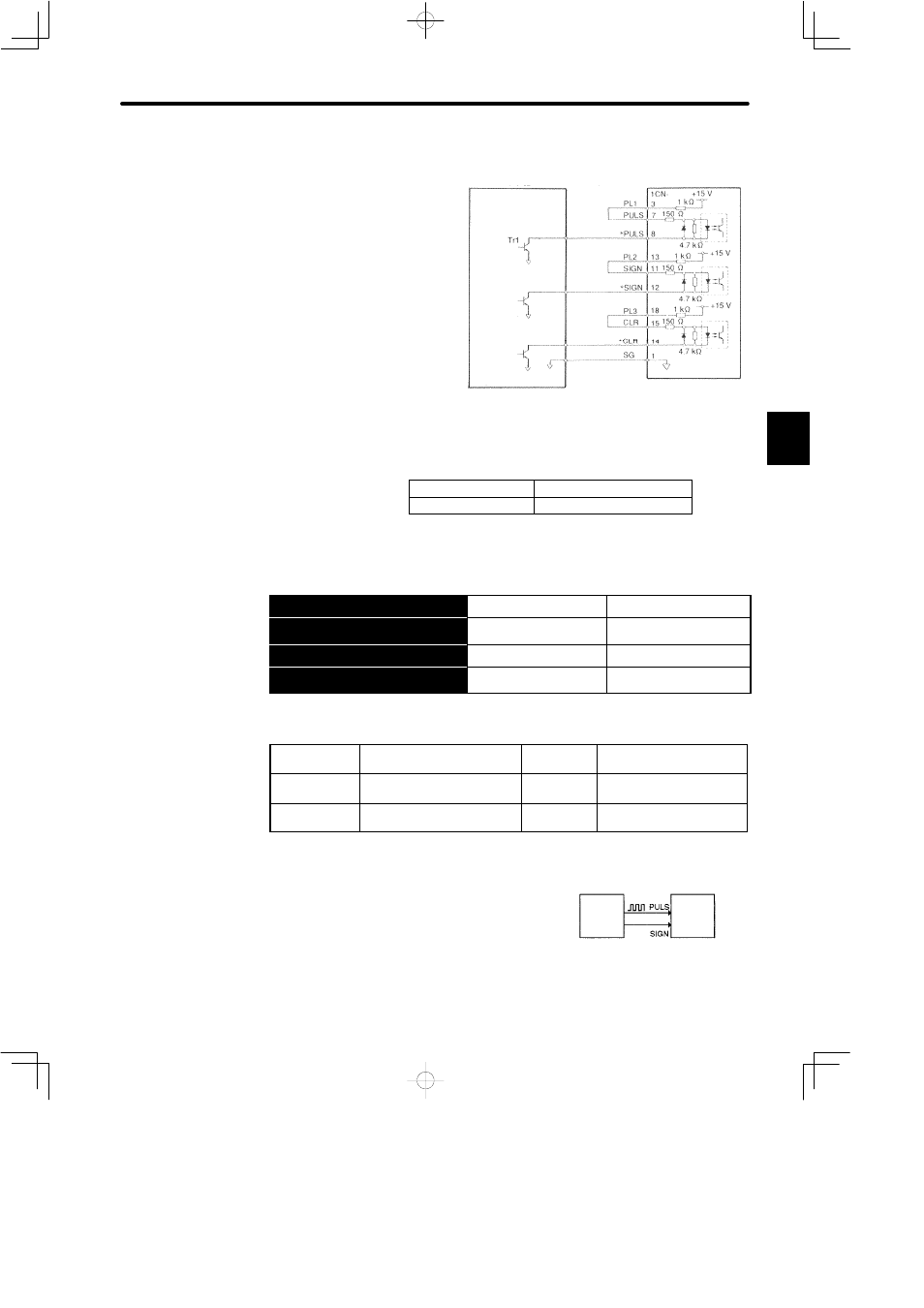
Connection Example 3: When Power for Open Collector Reference is Used
When power for open collec-
tor reference (PL1, PL2,
PL3) is used, connect be-
tween PL1 and PULS, PL2
and SIGN, PL3 and CLR as
follows:
Note The signal logic for open collector output is as follows.
When Tr1 is ON
Equivalent to high level input
When Tr1 is OFF
Equivalent to low level input
3) Use the following memory switch to select the reference pulse form to be used:
→ Input PULS
1CN-7
Reference Pulse Input
For Position Control Only
→ Input
£
PULS 1CN-8
Reference Pulse Input
For Position Control Only
→ Input SIGN
1CN-11
Reference Sign Input
For Position Control Only
→ Input
£
SIGN
1CN-12
Reference Sign Input
For Position Control Only
The motor only rotates at an angle proportional to the input pulse.
Cn-02 Bit 3
Reference Pulse Form
Selection
Factory
Setting: 0
For Position Control Only
Cn-02 Bit 4
Reference Pulse Form
Selection
Factory
Setting: 0
For Position Control Only
Cn-02 Bit 5
Reference Pulse Form
Selection
Factory
Setting: 0
For Position Control Only
Sets the form of a reference pulse that is external-
ly output to the Servopack.
Sets the pulse form according to the host control-
ler specifications.
Set also the input pulse logic in bit D of Cn-02.
3
Host controller
Servopack
Photo-
coupler
↕P: Represents twisted-pair cables
Host
controller
Position
reference
pulse
Servopack
(1CN-7)
(1CN-11)