Yaskawa DR2 Sigma Servo User Manual
Page 55
2.4 Conducting a Test Run
41
If the signal lines below are not wired correctly, the motor fails to rotate. Always wire
them correctly. (If signal lines are not to be used, short them as necessary.)
P-OT
1CN-42
Motor can rotate in forward direction when this input signal is at 0 V.
N-OT
1CN-43
Motor can reverse when this input signal is at 0 V.
S-ON
1CN-40
Servo is turned ON when this input signal is at 0 V. However, leave
the servo in OFF status.
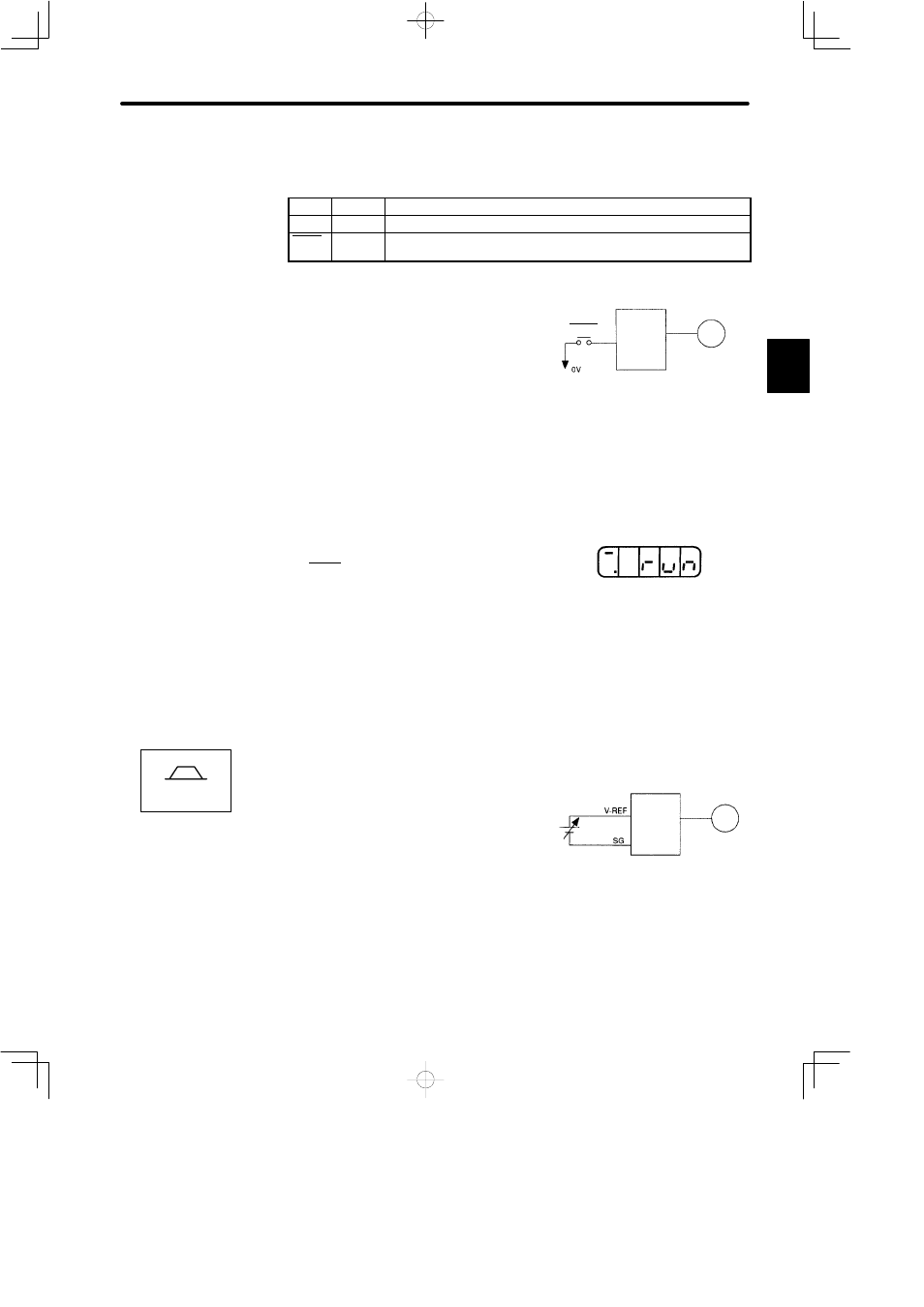
(8) Turn servo (motor) ON.
Turn the servo ON as follows:
(1) Check that no reference has been input.
Speed/torque control mode :
V-REF (1CN-5) and T-REF (1CN-9) are at 0 V.
Position control mode:
PULS (1CN-7) and SIGN (1CN-11) are fixed.
(2) Turn the servo ON signal ON.
Set S-ON (1CN-40) to 0 V. If normal, the motor
is turned ON and the Digital Operator displays
the data as shown in the figure. If an alarm dis-
play appears, take appropriate action as de-
scribed in Appendix E List of Alarm Displays.
(9) Operate by reference input.
The operating procedure differs according to the Servopack control mode used.
Speed/Torque Control Mode
(This section describes the standard speed con-
trol setting.)
(1) Gradually increase the speed reference input
(V-REF, 1CN-5) voltage. The motor will rotate.
When a host controller such as a programmable controller performs position
control, it may be difficult to directly input the speed reference voltage. In this
case, constant voltage reference should be input once to ensure correct opera-
tion.
2
Servopack
Servomotor
Turn the servo ON
S−ON
(1CN−40)
Display when servo is turned ON
Speed/Torque
Servopack
Servomotor
Servomotor rotates at a speed
proportional to the reference voltage.
(1CN−5)
(1CN−6)