Yaskawa DR2 Sigma Servo User Manual
Page 466
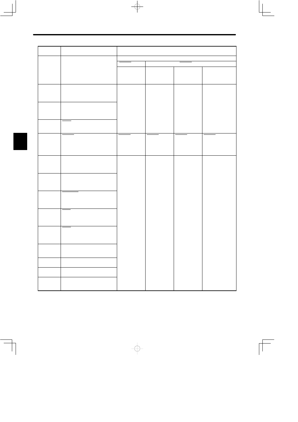
LIST OF I/O SIGNALS
456
Specifi-
cations
Standard Specifications
Torque Control II
Memory
S i h
Standard Setting
(C 02 bi B 0)
Cn-01 Bit A = 1, B = 1
y
Switch
Setting
g
(Cn-02 bitB = 0)
P-CON = OFF
P-CON = ON
Setting
−
Cn-01
Bit F = 0
Cn-02
Bit F = 0
Cn-01
Bit F = 0
Cn-02
Bit F = 1
Cn-01
Bit F = 1
Cn-02
Bit F = 1 or 0
38
ALO2
Alarm code output
(Open collector)
3.7.1
39
ALO3
Alarm code output
(Open collector)
3.7.1
40
S-ON
Servo on input
3.7.2
41
P-CON
P control input
3.6.4
P-CON
Torque/speed
control switch
3.2.7
P-CON
Torque/speed
control switch
3.2.7
P-CON
Torque/speed
control switch
3.2.7
P-CON
Torque/speed
control switch
3.2.7
42
P-OT
Forward rotation prohibited
3.1.2
43
N-OT
Reverse rotation prohibited
3.1.2
44
ALM-RST
Alarm reset input
3.7.1
45
P-CL
Forward torque limit ON input
3.1.3
46
N-CL
Reverse torque limit ON input
3.1.3
47
+24VIN
I/O power supply
3.2.4
48
−
(Unused)
49
−
(Unused)
50
FG
Frame ground
3.2.3
Note
Information described in the “Standard Specifications” column is also applicable to blank col-
umns.
Number “x.x.x” in box represents a section number corresponding to each signal name. For
example,
3.2.3
represents Section 3.2.3.
C