Yaskawa DR2 Sigma Servo User Manual
Page 461
451
Specifi-
cations
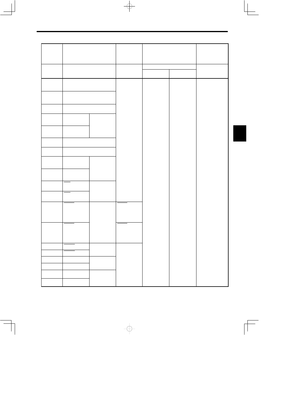
Speed Control
with Torque Limit
by Analog
Voltage
Reference
Contact Input Speed Control
Brake
Interlock
Output
Standard Specifications
Memory
Switch
Setting
Cn-02
Bit F = 1
Cn-02 Bit 2 = 1
Cn-01 Bit E
Standard Setting
(Cn-02 bitB = 0)
Memory
Switch
Setting
Cn-02
Bit F = 1
Cn-01
Bit B = 1
Cn-01
Bit B = 0
Cn-01 Bit E
Standard Setting
(Cn-02 bitB = 0)
16
TRQ-M
Torque monitor
3.2.12
17
VTG-M
Speed monitor
3.2.12
18
−
(Unused)
19
PCO
PG signal
output
phase-C
20
*PCO
phase C
3.2.3
21
−
(Unused)
22
−
(Unused)
23
+15V
Power for
speed/
torque
24
-15V
torque
reference
3.2.1
25
CLT+
Torque limit
detection
output
26
CLT-
output
3.1.3
27
TGON+
TGON output
signal
TGON+
Brake interlock
signal
3.4.4
28
TGON-
3.7.5
TGON+
Brake interlock
signal
3.4.4
29
S-RDY+
Servo ready
output
30
S-RDY-
output
3.7.6
31
ALM+
Servo alarm
output
32
ALM-
output
3.7.1
33
PAO
PG signal
output
34
*PAO
output
phase-A
3.2.3
C