2 inputting position reference – Yaskawa DR2 Sigma Servo User Manual
Page 82
3.2 Setting User Constants According to Host Controller
69
3.2.2 Inputting Position Reference
1) Using the following memory switch, select the position control.
Cn-02 Bit B
Selection of Speed/Torque
Control or Position Control
Factory
Setting: 0
For Speed/Torque Control
and Position Control
Select the control mode (speed/torque control or position control) by bit B of memory
switch Cn-02.
Setting
Meaning
0
Selects speed or torque control.
Select the control form by bits A and B of memory switch Cn-01.
1
Selects position control.
Note For the memory switch Cn-02, always turn the power OFF and then ON after
changing the setting. This makes the new setting valid.
2) Input a position reference by using the following input signal “reference pulse input.”
Since there are several specifications for input signal, select reference input for the sys-
tem to be created.
Inputs a move reference by pulse
input.
Position reference can correspond
to the following three types of out-
put form:
• Line driver output
• +12V Open collector output
• +5V Open collector output
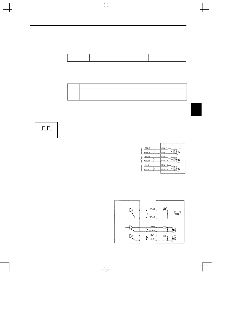
Connection Example 1: Line Driver Output
Line Driver Used:
SN75174 manufactured by
Texas Instruments Inc., or
MC3487 or equivalent.
3
Positions
Reference pulse
input
Reference sign
input
Error counter
clear input
Servopack
↕P: Represents twisted-pair cables
PHOTOCOUPLER
Host controller
Line driver
Servopack
Photocoupler
1CN-7
1CN-8
1CN-11
1CN-12
1CN-15
1CN-14