Yaskawa DR2 Sigma Servo User Manual
Page 467
457
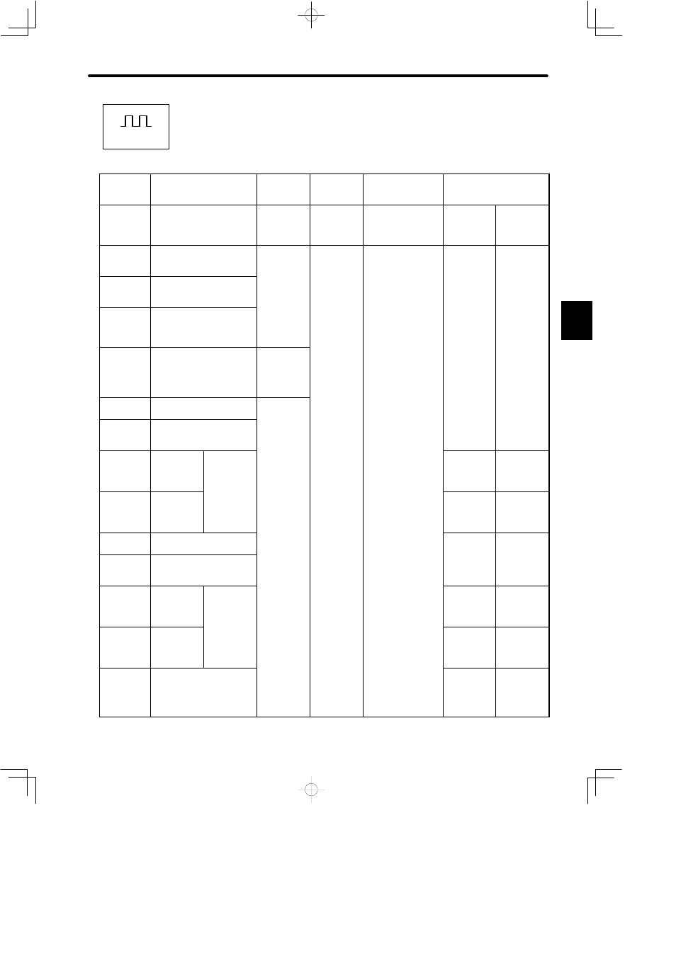
List of I/O Signals IN Position Control Mode (1)
(1CN Terminal No.)
Specifi-
cations
Standard Specifications
Absolute
Encoder
Brake
Interlock
Output
INHIBIT
Input
Contact Input Speed
Control
Memory
Switch
Setting
Standard Setting
(Cn-02 Bit B = 1)
Cn-02
Bit 9 = 1
Cn-01
Bit E = 1
Cn-01 Bit F = 1
Cn-02 Bit 2 = 0
Cn-01 Bit F
= 0
Cn-02 Bit 2
= 1
Cn-01 Bit F
= 1
Cn-02 Bit 2
= 1
1
SG
GND
2
SG
GND
3
PL1
Power for open collector
reference
3.2.2
4
−
(Unused)
SEN
Sensor ON
signal
3.8.5
5
−
(Unused)
6
SG
GND
7
PULS
Reference
pulse input
3 2 2
−
(Unused)
3.2.6
PULS
Reference
pulse input
3.2.2
8
*PULS
3.2.2
−
(Unused)
3.2.6
*PULS
Reference
pulse input
3.2.2
9
−
(Unused)
10
SG
GND
11
SIGN
Reference
sign input
3 2 2
−
(Unused)
3.2.6
PULS
Reference
pulse input
3.2.2
12
*SIGN
3.2.2
−
(Unused)
3.2.6
*PULS
Reference
pulse input
3.2.2
13
PL2
Power for open collector
reference
3.2.2
C
Positions