Yaskawa DR2 Sigma Servo User Manual
Page 470
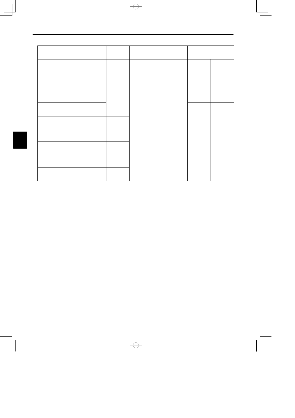
LIST OF I/O SIGNALS
460
Specifi-
cations
Contact Input Speed
Control
INHIBIT
Input
Brake
Interlock
Output
Absolute
Encoder
Standard Specifications
Memory
Switch
Setting
Cn-01 Bit F
= 1
Cn-02 Bit 2
= 1
Cn-01 Bit F
= 0
Cn-02 Bit 2
= 1
Cn-01 Bit F = 1
Cn-02 Bit 2 = 0
Cn-01
Bit E = 1
Cn-02
Bit 9 = 1
Standard Setting
(Cn-02 Bit B = 1)
46
N-CL
Reverse torque limit ON
input
3.1.3
N-CL
Contact
input speed
control 2
3.2.6
N-CL
Contact
input speed
control 2
3.2.6
47
+24VfIN
I/O power supply
3.2.4
48
−
(Unused)
PSO
Phase-S
signal
output
3.8.5
49
−
(Unused)
*PSO
Phase-S
signal
output
3.8.5
50
FG
Frame ground
3.2.3
Note
Information described in the “Standard Specifications” column is also applicable to blank col-
umns.
Number “x.x.x” represents a section number corresponding to each signal name. For exam-
ple,
3.2.3
represents Section 3.2.3.
C