Input clr 1cn-15, Input, Clr 1cn-14 – Yaskawa DR2 Sigma Servo User Manual
Page 87

APPLICATIONS OF Σ-SERIES PRODUCTS
3.2.2 Inputting Position Reference cont.
74
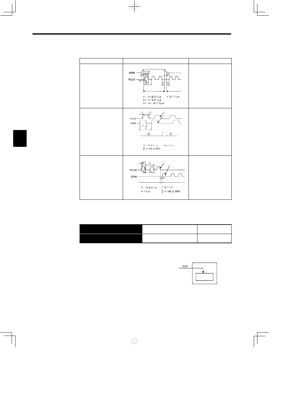
Allowable Voltage Level and Timing for Reference Pulse Input
Reference Pulse Form
Electrical Specifications
Remarks
Sign + pulse train input
(SIGN + PULS signal)
Maximum reference
frequency: 450 kpps
¨
reference
©
reference
The signs for each
reference pulse are as
follows:
¨
: High level
©
: Low level
90° different two-phase
pulse train
(phase A + phase B)
Maximum reference
frequency
x 1 multiplier:
450 kpps
x 2 multiplier:
400 kpps
x 4 multiplier:
200 kpps
Phase A
Phase B
Phase B is 90°
forward from phase B
Phase B is 90°
behind phase B
User constant Cn-02
(bits 3, 4 and 5) is used
to switch the input pulse
multiplier mode.
CCW pulse + CW pulse
Maximum reference
frequency: 450 kpps
CCW pulse
CW pulse
¨
reference
©
reference
4) The following describes how to clear the error counter.
→ Input CLR 1CN-15
Error Counter Clear Input
For Position
Control Only
→ Input
£
CLR 1CN-14
Error Counter Clear Input
For Position
Control Only
Setting the CLR signal to high level does the fol-
lowing:
• Sets the error counter inside the Servopack to 0.
• Prohibits position loop control.
Use this signal to clear the error counter from the
host controller.
Bit A of memory switch Cn-02 can be set so that the error counter is cleared only once
when the leading edge of an input pulse rises.
3
Servopack
Clear
Position loop
error counter