Yaskawa DR2 Sigma Servo User Manual
Page 165
APPLICATIONS OF Σ-SERIES PRODUCTS
3.8.5 Using an Absolute Encoder cont.
152
SEN signal
• The SEN signal must be set at high level af-
ter at least three seconds after the power is
turned ON.
• When the SEN signal is changed from low
level to high level, +5 V is applied to the ab-
solute encoder, and serial data and initial in-
cremental pulses are transmitted.
• The motor is not turned ON until these operations are complete, regardless of the servo
ON signal (S-ON).
3) Memory Switch to Determine Whether to Use Input Signal SEN
Cn-01 Bit 1
Use of SEN Input Signal
Factory
Setting: 0
For Speed/Torque Control
and Position Control
This memory switch is used to determine whether
to use input signal SEN (1CN-4).
This memory switch is available for absolute en-
coders only (not for incremental encoders).
Setting
Meaning
0
Uses SEN signal.
1
Does not use SEN signal.
NOTE
If the SEN signal is to be turned OFF, then ON again, it must remain at high level for at
least 1.3 seconds before being turned OFF.
SEN signal
OFF
ON: High level
ON
1.3 seconds or more
15 ms
or more
OFF
4) Memory Switch to 1 to Select Absolute Encoder
Cn-02 Bit 9
Encoder Type Selection
Factory
Setting: 0
For Speed/Torque Control
and Position Control
Sets the encoder type according to the servomotor type to be used.
After changing the memory switch setting, turn the power OFF, then ON.
Motor Type
Number of Encoder Pulses Per Revolution
Preset
Value
SGM-jjj31j
SGMP-jjj31j
Incremental encoder: 2048 pulses per revolution
0
SGM-jjjW1j
SGMP-jjjW1j
Absolute encoder
:
1024 pulses per revolution
1
3
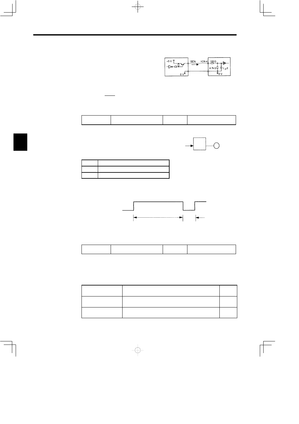
Electrical Specifications
Host controller
At high level
Approx. 1mA
7406 or
equivalent
Servopack
• A PNP transistor is recommended.
• Signal level High level: Min. 4 V
Low level: Max. 0.7 V
SG
1CN-2
Servopack
Servomotor
Absolute encoder
1CN-4
SEN