Yaskawa DR2 Sigma Servo User Manual
Page 334
SERVO SELECTION AND DATA SHEETS
5.4.2 Servomotor Dimensional Drawings cont.
322
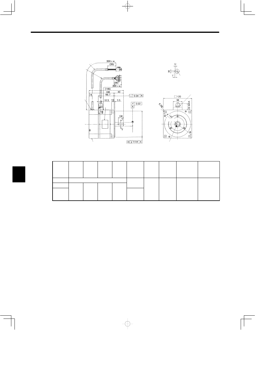
• 750 W (1.01HP)
(1.10)
12−bit Absolute
Encoder 1024 P/R
Cross-section Y-Y
4-φ10
(φ0.39)
MTG Holes
Motor Lead
UL2464
φ7 (φ0.29)
Sealant
(0.0016)
(0.0008)
(5.75)
(11.81¦1.18)
(1.38)
(0.14)
(11.81¦1.18)
11
0
0 -0.035
4.33
-0.0014
0
φ
(
)
(4.17)
(4.72)
(0.39)
Marked Wire
Nameplate
φ
16
0 -0.01
1
0.63
-0.0004
0
φ
(
)
(φ0.0016)
Encoder Lead
UL20276φ8
(φ0.31)
(1.38)
(1.57)
(1.50)
(0.41)
Screw
Hex. Nut
17 (0.67)
(φ5.71)
(2.63)
(0.75)
(0.55)
φ
Shaft end screw hole
(SGMP-08VW16, with key type only)
Type
SGMP-
QK
U
W
T
Screw
dimen-
sions
Output
W
(HP)
Approx.
mass
kg
(lb)
Allowable
radial load
N (lb)
Allowable
thrust load
N (lb)
08VW12 No key
−
750
(
)
4.7
(
)
392 (88.1)
147 (33.0)
08VW14 22
(
)
3
(
)
5
(
)
5
(
)
(1.01)
(10.36)
(
)
(
)
08VW16 (0.87)
(0.12)
(0.20)
(0.20)
M5,
depth 8
(0.31)
Note
1) The detector uses a 12-bit absolute encoder 1024 P/R.
2) Type “V” indicates 200 V specification.
3) “08VW14” and “08VW16” have a keyed shaft. The keyway complies with JIS B
1301-1976 (precision). A straight key is supplied.
4) The quoted allowable radial load is the value at a position 35 mm (1.38 in.) from the mo-
tor mounting surface.
5) Conforms to IP55 protective structure (except connector and output shaft faces).
5