B.1 sigma-series ac servopack gain adjustment, B.1 σ -series ac servopack gain adjustment – Yaskawa DR2 Sigma Servo User Manual
Page 441
SERVO ADJUSTMENT
B. 1 .1 Σ -Series AC Servopacks and Gain Adjustment Methods
430
B.1 Σ-Series AC Servopack Gain Adjustment
This section gives some basic information required to adjust the servo system.
B.1.1
Σ-Series AC Servopacks and Gain Adjustment Methods
430
. . . . . . . . . . . . . . . . . . . .
B.1.2
Basic Rules for Gain Adjustment
431
. . . . . . . . . . . . . . . . . . . . . . . . . . . . . . . . . . . . . . . . .
B.1.1 Σ-Series AC Servopacks and Gain Adjustment Methods
1) Five types of Σ-Series AC Servopack are available: DR1, SGDA, SGDB, SGD and the
current DR2.
The adjustment method is basically identical for each Servopack type, except that auto-
tuning is not available for some types.
The DR2, SGDA,SGDB and SGD Servopacks allow both manual adjustment by the con-
ventional method of observing the machine response and automatic adjustment using
the internal auto-tuning function. The DR1 Servopack does not offer auto-tuning.
2) The main user constants changed by the customer to adjust the servo system include the
following:
• Cn-04 (Speed Loop Gain)
• Cn-05 (Speed Loop Integration Time Constant)
• Cn-17 (Torque Reference Filter Time Constant)
• Cn-1A (Position Loop Gain)
In a speed-control Servopack (where speed references are applied as analog voltages),
the position loop is controlled by the host controller, so the position loop gain is normally
adjusted at the host controller.
If adjustment is not possible at the host controller, the same adjustment can be achieved
using Cn-03 (Speed Reference Gain), but the servomotor may not reach maximum
speed for some preset values of this user constant.
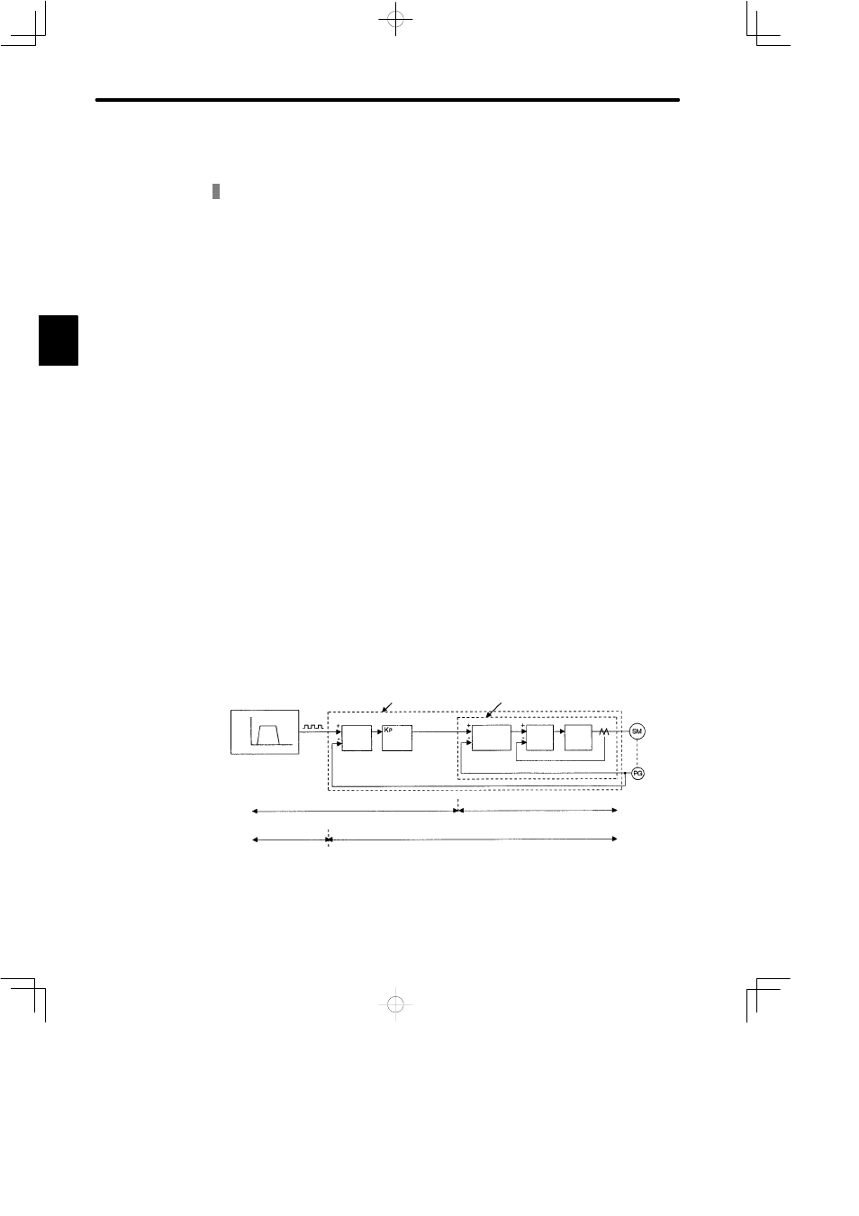
A simple block diagram of the servo system is shown below.
Servo System Block Diagram
Speed Speed
Pattern
Time
Pulse
Train
Position-control Servopack Speed-control Servopack
Error
Count-
er
Position Control Loop
(D/A
Convert-
er)
Analog Voltage
Speed Control Loop
Speed
Control
Section
Current
Control
Section
Power
Con-
verter
Motor
Encoder
Using Speed-control
Servopack
Host Controller (supplied by customer)
Servopack
Using Position-control
Servopack
Host Controller
(supplied by
customer)
Servopack
Kp: Position Loop Gain
Kv: Speed Loop Gain
Ti: Integration Time Constant
Note:
A position-control Servopack has no D/A converter for speed reference
output. This conversion is handled by internal calculations.
B