Rockwell Automation 9323-S5500D A.I. SERIES MICROLOGIX 1000 AND PLC-500 SOFTW User Manual
Page 479
MicroLogix 1000 and PLC-500 A.I. Series Software Reference
19-48
[F5]
Tchart
run a timing chart on the highlighted address
[F7]
Dualscr
enter the dual screen mode (only available if using a high resolution
video mode. See
Programming Screen Size
in
Chapter 12 -
Customizing PLC-500 A.I.
)
[F8]
Btoggl
toggle the value of the bit under the cursor (for bit addresses only)
[F9]
Adrmode
toggle between displaying addresses and symbols
Data Entry
You can use custom data monitoring screens to change the values of addresses. The
data entry prompt for the current cell appears in the lower left corner of the screen.
To change an address value (in monitor mode):
1.
Move the cursor to the cell containing the value that you want to change.
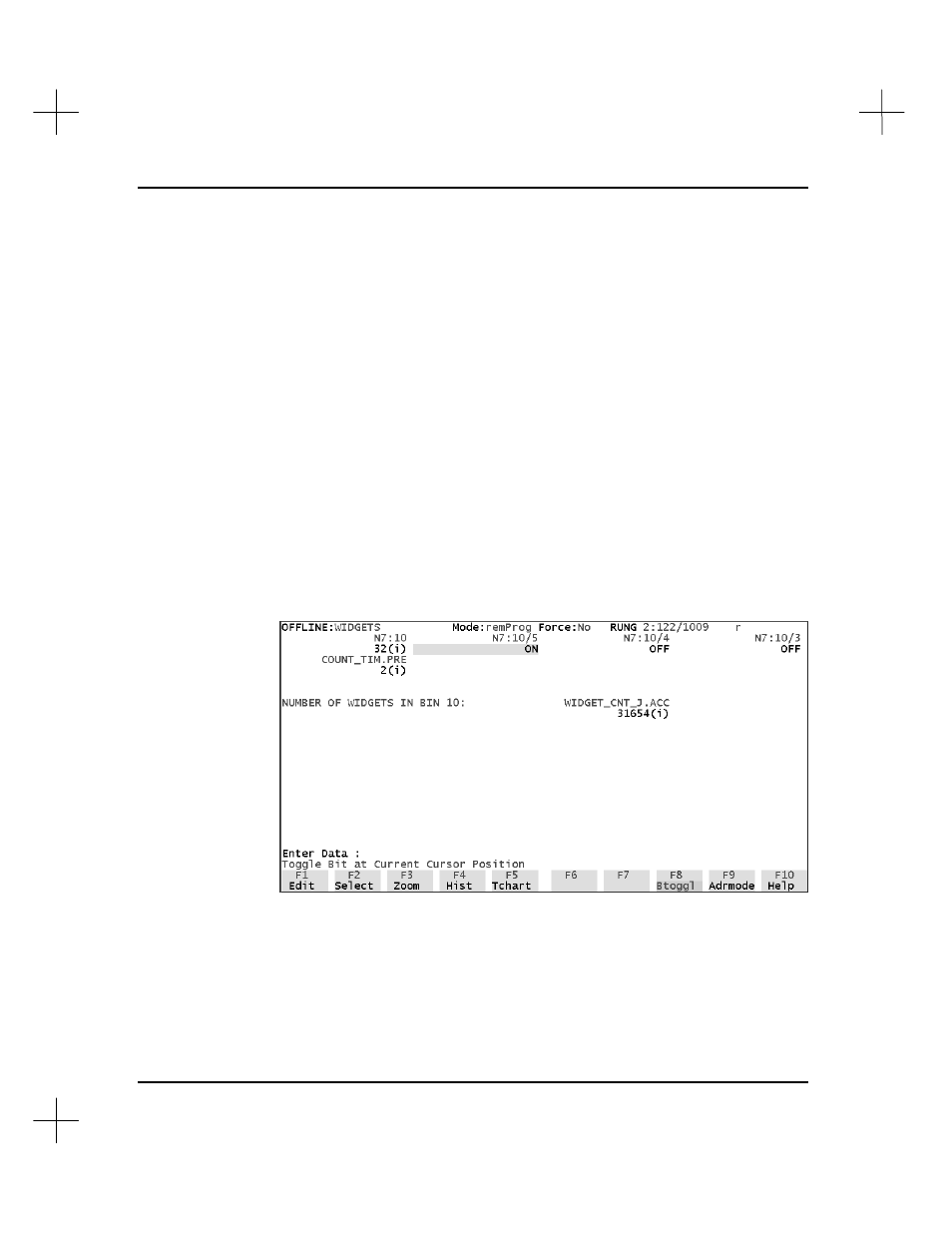
2.
Type the new value for that address. For binary addresses, type ON, OFF, 1 or 0,
or simply press
[F8]
Btoggl
to toggle the value. Notice in the screen below that
toggling the value for bit N7:10/5 also changed the value for word N7:10.
(Compare to the screen on the previous page.)
You can also toggle between address and symbol display modes with
[F9]
Adrmode
.
Valid data entry format depends on the radix for the current cell. For example, a cell
containing an integer address formatted as BCD will interpret input as a BCD value
(e.g., 27 BCD = 39 integer).