Monitoring output and input files – Rockwell Automation 9323-S5500D A.I. SERIES MICROLOGIX 1000 AND PLC-500 SOFTW User Manual
Page 79
Data Table Addressing and Editing
4-11
Monitoring Output and Input Files
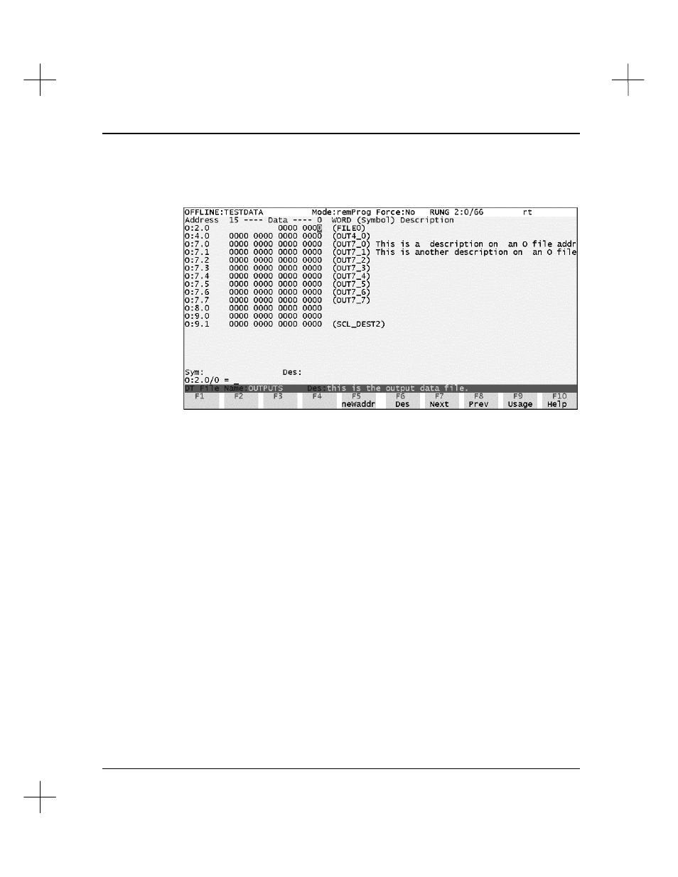
When monitoring output and input files, the file monitor screen appears as follows:
The following function keys are active on this screen:
[F5]
neWaddr
Allows you to enter a different address to display.
[F6]
Des
Starts the instruction description editor for the highlighted address.
[F7]
Next
Displays the monitor screen for the next data table file.
[F8]
Prev
Displays the monitor screen for the previous data table file
[F9]
Usage
(or
Value
)
Displays usage information for the file. An “
X
” indicates that the
ladder logic in any one of your program files uses a particular bit or
word. A “
.
” indicates that the bit or word is unused. To return to
displaying values, press
[F9]
Value
. The Usage screen contains an
extra
WF
column. A
W
in this column means the address is used as
a word; an
F
means the address is part of a group of addresses (file).
See
Monitoring Integer Files
for an example.
[F10]
Help
Displays information about using this screen.