Selecting a slc 500 address or operand, Addressing modes – Rockwell Automation 9323-S5500D A.I. SERIES MICROLOGIX 1000 AND PLC-500 SOFTW User Manual
Page 97
Data Table Addressing and Editing
4-29
Selecting a SLC 500 Address or Operand
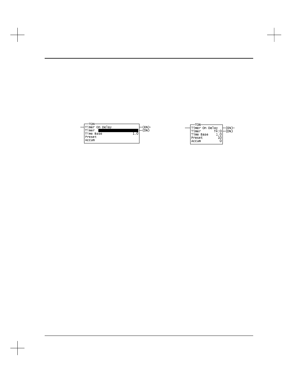
When you insert or append an instruction into a ladder program, the system asks you to
specify addresses for the instruction. For example, the illustration below shows a timer
instruction before and after addresses and values are specified.
For additional information about instruction requirements, use the Instruction Help
facility (use the command portal string
.UUKI
or
[Shift-F10]
). While programming
an instruction, you can press
[F10]
to get help on that specific instruction.
Addressing Modes
The SLC 500 processor supports a number of different addressing modes.
Logical Addressing
Logical Addresses consist of an alpha-numeric string with punctuation to specify the
data location. For instance, N7:50 represents the 51
st
word in file N7. (Remember, the
first element in any file is “0”.)
Indexed Addressing
Indexed Addresses (SLC 5/02, 5/03, 5/04, and MicroLogix processors) consist of a
prefix (#) followed by a logical address referred to as a base address. An offset value
from the processor status file word S:24 is added to the base address. For example, if
S:24 has a value of 12, then the indexed address #N7:10 would actually reference
N7:22 in the data table.
After Specifying
Addresses
Before Specifying
Addresses