Yaskawa MotionSuite Series Machine Controller Software Manual User Manual
Page 188
MotionSuite™ Series Machine Controller Software Manual
Chapter 7: System Data Definition
7-15
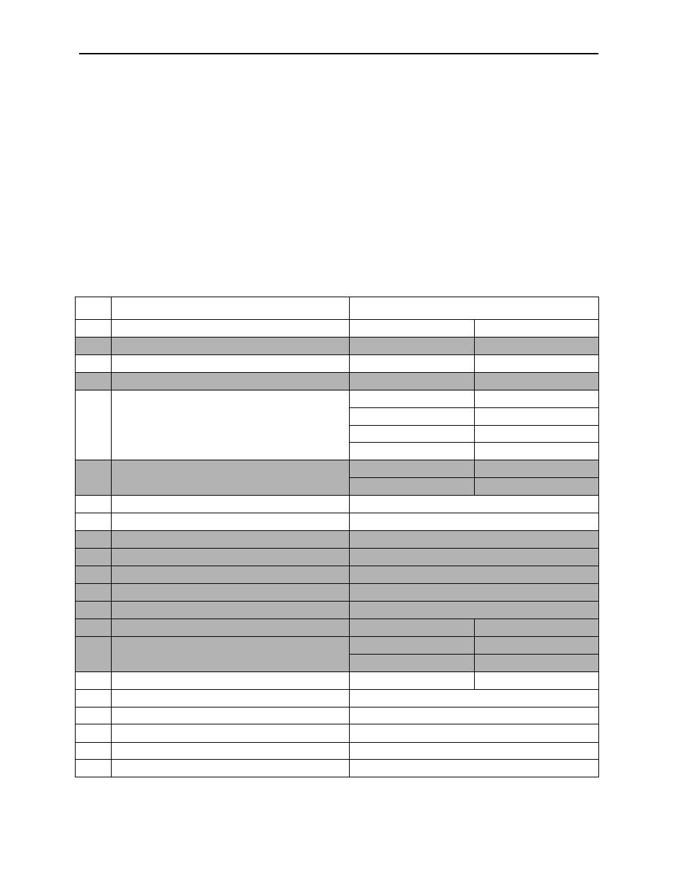
1. Group Name
Selects the group name set in the group definition.
2. Logical Axis Name
The logical axis name is displayed. Fixed parameters are set in axis units.
3. Parameter Name
The parameter name is displayed.
4. Setting Data
Input (select) the parameter values. The content of the settings of each parame-
ter are shown in Table 5 below. The setting values of the shaded items cannot be
changed.
Table 5: Setting Data of Fixed Parameters
No.
Fixed Parameter
Setting Data
1
Axis Used Selection
Unused selection
Used Selection
2
PG Signal Status Selection
+5V differential input
+12V collector input
3
Encoder Selection
Incremental Encoder
Absolute Encoder
4
Motor Rotating Direction (with absolute enc.)
Forward
Backward
5
Pulse Counting Form Selection
+/- format
×1
+/- format
×2
Up/Down
×1
Up/Down
×2
A/B format
×1
A/B format
×2
A/B format
×4
6
Counter Mode Selection
Reversible counter
Interval counter
Frequency estimation
Basic counter
7
Rated Speed
1~32000 (1=1rpm)
8
Number of Encoder Pulses
Multiples of four in 4~65532 (1=1P/R)
9
D/A Output Voltage at 100% Speed
1~10 (1=1V)
10
D/A Output Voltage at 100% Torque Limit
1~10 (1=1V)
11
D/A Input Voltage at 100% Speed Monitor (D/A)
1~10 (1=1V)
12
D/A Input Voltage at 100% Torque Monitor (A/D)
1~10 (1=1V)
13
DI Latch Detection Signal Selection
DI INT input signal
14
Coincidence Detection Used Selection
Not used
Used
15
Frequency Coefficient Selection
×10 (0.1Hz)
×100 (0.01Hz)
×1000 (0.001Hz)
×1 (1Hz)
16
Simulation Mode Selection
Normal run mode
Simulation mode
17
Servo Module Function Select Flag
See Figure 1
18
Number of Decimal Places
0~5
19
1 Machine Rotation/Command Unit
1~2147483647 (command unit)
20
Gear Ratio ( motor side)
1~65535
21
Gear Ratio ( load side)
1~65535