Table data input – Yaskawa MotionSuite Series Machine Controller Software Manual User Manual
Page 317
MotionSuite™ Series Machine Controller Software Manual
Chapter 8: Ladder Programming
8-69
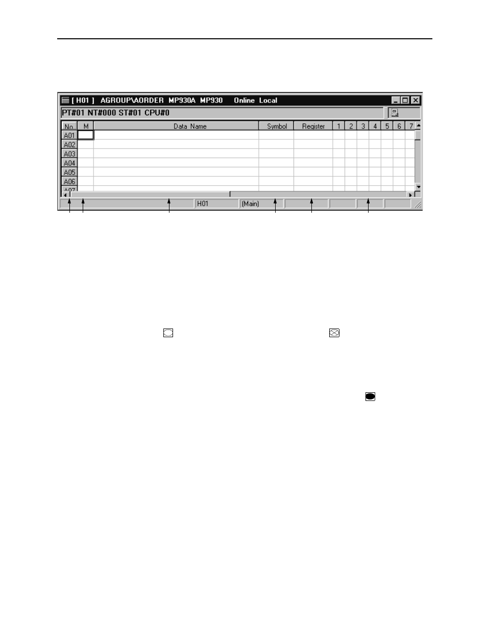
Table Data Input
Table data can be input up to 500 rows and 25 columns.
1. Number
Shows the row number for each block. The block numbers are shown with the
letters A ~ Z, the numbers following are the column numbers.
2. Mode
Input the interlock conditions input mode with the letter I, S, O or X.
I:
Input I when defining an input signal. The signal input to the line 1 ~ xx
of the column which defined this mode sets normally open (NO) contacts
to ( ), and normally closed (NC) contacts to ( ).
S:
Input S when inputting table data into a sub-table. This mode is enabled
only in a main table. The sub-table output and main table input symbols
(or registers) must be identical.
O:
Input O when defining the output signal. The signal input to column
1 ~ xx of the row which defined this mode sets coils to ( ).
X:
Input X when defining an output signal as an input signal. Input to the
Input Register box is necessary when X is input. However, be sure that
the same symbol outputs are defined in the main table in the case of a
main table, and the sub-1 table in the case of a sub-1 table.
3. Data Name
Input a name of 48 16-bit characters (24 32-bit characters) or less. 16-bit and 32-
bit characters can be combined within names.
4. Symbol
Input a symbol pertaining to the register number subject to interlock in 8 16-bit
characters (4 32-bit characters) or less. 16-bit and 32-bit characters can be com-
bined in this entry.
1
2
3
4
5
6