5 monitor parameters – Yaskawa MotionSuite Series Machine Controller Software Manual User Manual
Page 199
MotionSuite™ Series Machine Controller Software Manual
Chapter 7: System Data Definition
7-26
6. Unit
This displays the parameter units.
7. Current Value
This column displays the current value of a servo amplifier parameter.
Supplement:
Default Value Setting
It is possible to omit the input of each parameter, and yet set the default values. The servo
parameters of the axis currently displayed are set into the default. See the Default Value
column in Table 9 for the default value of each parameter. The setting method of the
default parameters is the same as that for the fixed parameters. See Item, 7.3.2 “Fixed
Parameter Setting.”
7.3.5
Monitor Parameters
The following screen is displayed upon clicking the Monitor Parameters tab in the
motion parameter window. The current values of the motion parameters are displayed
in this screen. This screen is for display only, and the individual settings cannot be
changed.
5
1= DEC signal delete, 0= DEC signal enabled
6
1= EXT signal delete, 0= EXT signal enabled
7~9
Reserved
A
P-OT signal direction: 1=Positive logic, 0= Negative logic
B
N-OT signal direction: 1=Positive logic, 0= Negative logic
C~F
Reserved
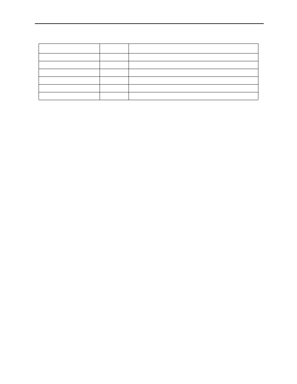
Table 10: Memory Switch Bit Structure for Parameters No. 1 and No. 2
Memory Switch Number
Bit No.
Content