Yaskawa MotionSuite Series Machine Controller Software Manual User Manual
Page 193
MotionSuite™ Series Machine Controller Software Manual
Chapter 7: System Data Definition
7-20
33
Step Movement Quantity
0~2
31
-1
1000
1=1 command unit
34
Zero Point Return Range
0
1=1 command unit
35
Override
0~32767
10000
1=0.01%
36
Position Management Control Flag
Bit setting
0000H
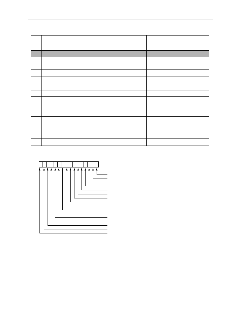
See Figure 5
37
Work Coordinate Offset
0~±2
31
-1
0
1=1 command unit
38
Number of POSMAX Turns Preset Data
0~±2
31
-1
0
1=1 command unit
39
2nd In-Position Width
0~65535
0
1=1 command unit
40
Zero Point Position Output Width
0~65535
10
1=1 command unit
41
Positioning Completion Check Time
0~65535
0
1=1msec
42
Network Servo User Parameter Number
Bit setting
0000H
See Figure 6
43
Network Servo User Parameter Setting
0~±2
31
-1
0
—
44
Encoder Position at Power Cutoff (low)
0~±2
31
-1
0
1=1 pulse
45
Encoder Position at Power Cutoff (high)
0~±2
31
-1
0
1=1 pulse
46
PULSE Absolute Position at Power Cutoff (low)
0~±2
31
-1
0
1=1 pulse
47
PULSE Absolute Position at Power Cutoff (high)
0~±2
31
-1
0
1=1 pulse
Table 7: Set-up Parameter Data (Continued)
No.
Parameter
Range
Default Value
Notes
F E D C B A 9 8 7 6 5 4 3 2 1 0
1: Speed control mode
Bits 0, 1, 3~5, and 7~F cannot be set or changed.
Figure 2: Bit Structure of Parameter No. 1, Run Mode
1: Torque control mode
1: Position control mode
1: Phase control mode
1: Zero-point return mode
1: Phase control test mode
1: Alarm clear
Position reference generation operation (1: disabled 0: enabled)
Reserved (set to 0)
Zero-point return direction (1: forward 0: backward)
1: Absolute position read request
1: Attribute prohibition (during reversible/interval counter)
1: Attribute readout request
1: DI latch detection request
1: Coincidence detection request
1: Phase control integral list