Yaskawa MotionSuite Series Machine Controller Software Manual User Manual
Page 194
MotionSuite™ Series Machine Controller Software Manual
Chapter 7: System Data Definition
7-21
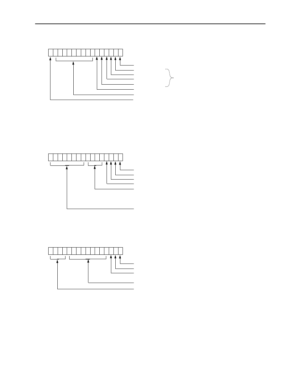
F E D C B A 9 8 7 6 5 4 3 2 1 0
1: Run
Bits 1~5 and F cannot be set or changed.
Figure 3: Bit Structure of Parameter No. 2, Drive Run Command
1: General DO
1: General DO
1: General DO
1: General DO
1: General DO (Coincidence detection signal)
Servo Drive
Run Command
Reserved (set to 0)
1: Zero-point Return Deceleration Point Limit Switch Signal
F E D C B A 9 8 7 6 5 4 3 2 1 0
1: Temporary Command Stop
Figure 4: Bit Structure of Parameter No. 29, Servo Command Flag
1: Command Interrupt
JOG/STEP Motion Direction (1: reverse 0: forward)
Speed loop P/PI Switching (1: P control 0: PI control)
Filter Type Selection
0000: No filter
0001: Exponent filter
0010: Motion average filter
Reserved (set to 0)
F E D C B A 9 8 7 6 5 4 3 2 1 0
Machine Lock Mode (1: ON 0: OFF)
Figure 5: Bit Structure of Parameter No. 36, Position Management Control Flag
1: Number of POSMAX Turns Reset Request
1: ABS System Infinite Position Management Data LOAD
Reserved (set to 0)
YENET Servo User Monitor Data Selection
Request (set to 0)
(Follow the YENET servo specifications for monitor data types)
Bit 2 can be neither set nor changed.