8 fault monitor data, 1 structure of the fault monitor window, Structure of the fault monitor window menu – Yaskawa MotionSuite Series Machine Controller Software Manual User Manual
Page 238
MotionSuite™ Series Machine Controller Software Manual
Chapter 7: System Data Definition
7-65
7.8 Fault Monitor Data
The MotionSuite™ series machine controllers are is equipped with a fault tracing func-
tion. Fault relays, fault levels, and failure names are defined in the fault monitor definition
window. The fault relays defined here display faults when the unit is in the ON state.
7.8.1
Structure of the Fault Monitor Window
Information on the fault monitor window menus and tabs appears below.
Structure of the Fault Monitor Window Menu
See Item 7.1.3, “Definition Screen Call-out” before opening the fault monitor window.
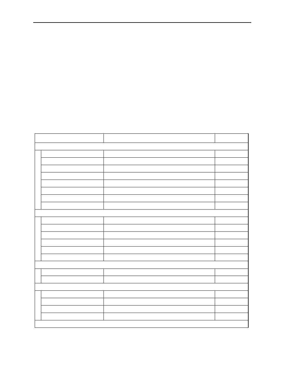
Table 19 shows the menus displayed in the fault monitor definition window. See the
item numbers shown in Table 19 when referring to any of the functions in the menu.
Table 19: Fault Monitor Definition Window Menu
Menu
Function
Item No.
File (F)
File Manager (F)
Opens File Manager
3.4.2
Open (O)
Opens various function windows
5.1
Close (C)
Closes the fault monitor definition window
7.8.9
Regist User Menu (U)
Registers user menu
—
Save (S)
Saves fault monitor definition data
7.8.7
Delete (D)
Deletes fault monitor definition data
7.8.8
Print (P)
Prints document
Ch. 12
Exit (X)
Exits Engineering Manager
3.4.2
Edit (E)
Insert (I)
Inserts blank row
7.8.2
Delete (D)
Deletes a number of connected rows
7.8.2
Cut (T)
Cuts row data
7.8.2
Copy (C)
Copies row data to cut buffer
7.8.2
Paste (P)
Copies contents of cut buffer
7.8.2
Comment (K)
Sets comments into failure names
7.8.2
Status (S)
Confirm (C)
Confirm status
—
Reset (R)
Reset status
—
View (F)
Tool Bar (T)
Displays tool bar
3.4.3
Status Bar (B)
Displays status bar
3.4.3
Next Page (N)
Displays next tab page
7.8.1
Back Page (N)
Displays previous tab page
7.8.1
Window (W)