5 i/o conversion table data input – Yaskawa MotionSuite Series Machine Controller Software Manual User Manual
Page 315
MotionSuite™ Series Machine Controller Software Manual
Chapter 8: Ladder Programming
8-67
4. Unit
Input parameter units of 8 16-bit characters (4 32-bit characters) or less. 16-bit
and 32-bit characters can be combined in this entry.
5. Lower Limit
Input the parameter lower limit.
6. Upper Limit
Input the parameter upper limit. Input so that Lower Limit
≤ Upper Limit.
7. Save Point
Input the M register to which the parameters are to be stored.
Note:
Setting, Lower Limit, Upper Limit, and Save Point must be set. An error occurs dur-
ing storage if these are not set.
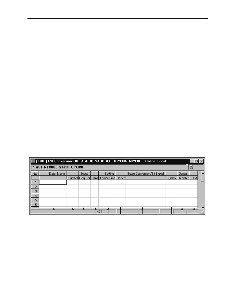
8.3.5
I/O Conversion Table Data Input
I/O conversion tables designate the input registers and conversion formats, and define
the output registers that store the converted results. When storing an I/O convert table,
the input register values are converted according to the conversion format and auto-
matically converted to a sub-program stored in the output register following an upper/
lower limit check. The sub-programs are referred to according to the XCALL com-
mands of the main program. Up to 100 rows of table data can be input.
1. Data Name
Input a name for each parameter of 36 16-bit characters (18 32-bit characters) or
less. 16-bit and 32-bit characters can be combined within names.
2. Input: Symbol
Input a symbol pertaining to the register number input in 8 16-bit characters (4
32-bit characters) or less. 16-bit and 32-bit characters can be combined in this
entry.
1
2
3
4
5
6
7
8
9
10