Routers – Grass Valley NV9000-SE v.3.0 User Manual
Page 126
106
Rev 3.0 • 25 Mar 10
7. Routers
Managing Virtual Crosspoints
3 Click anywhere in the row listing the router being updated and click
Edit Selected Routers
.
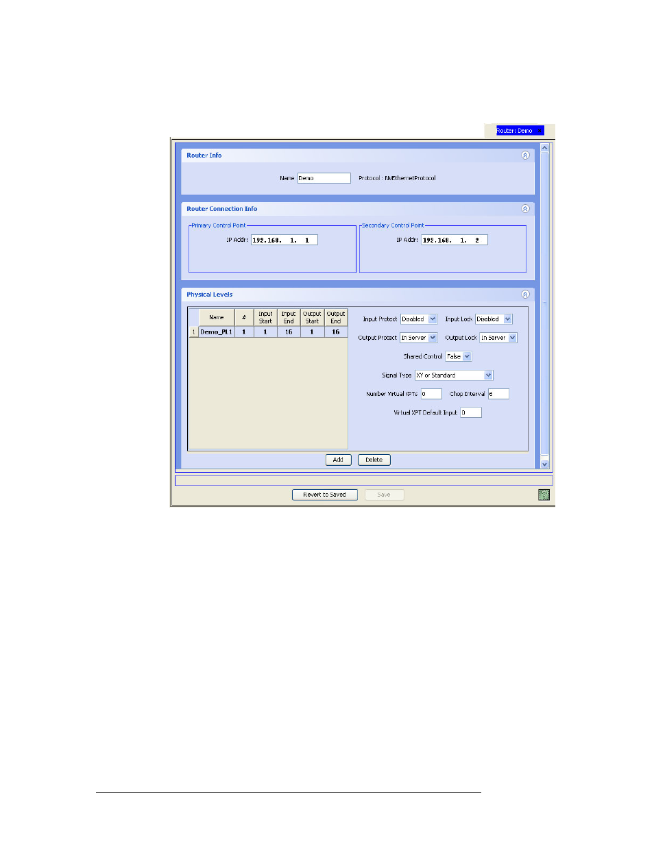
The ‘Router Details’ page appears:
Figure 7-36. Router Details Page, Example of Ethernet Connection
4 In the ‘Physical Levels’ section, enter the number of virtual crosspoints for the router in the
‘Number Virtual XPTs’ field.
Each physical level defined for the router can have a distinct number of virtual crosspoints. All
the options to the right of the physical level table apply to the selected physical level if the
router has more than one, and to the single physical level if the router has only one.
The crosspoint numbering extends the range of inputs and outputs declared for the physical lev-
els. If the input range is 1–64 and the output range is 1–32, and the number of virtual cross-
points is 4, the virtual input numbers are 65–68 and 33–36 for virtual outputs. In this example,
we would say that output 33 re-enters on input 65. (Keep in mind that this effect is simulated.)
5 In the ‘Physical Levels’ section, enter the ‘Virtual XPT Default Input’ in the field provided.
Route a physical input to a virtual output. Route the re-entered virtual input to an actual output.
This effectively routes the physical input to the physical output and allows any other output to
be routed to the re-entered input as well.
6 Repeat steps 4 and 5 for as many “virtual routes” as you need.