Control panels – Grass Valley NV9000-SE v.3.0 User Manual
Page 310
290
Rev 3.0 • 25 Mar 10
11. Control Panels
Adding a Control Panel
4 In the ‘Button Layout’ section, select a blank button and then in the ‘Button Definitions’ sec-
tion, select a definition for the button from the drop-down list. The button definition appears on
the selected button in the ‘Button Layout’ section.
There are two classes of buttons:
• Those that assign a dedicated function to a button directly, such as ‘Def State’ (default state)
or ‘Clear’. No other options are available.
• Those that define a variable function, such as ‘Category’. Additional options display
enabling you to define the variables.
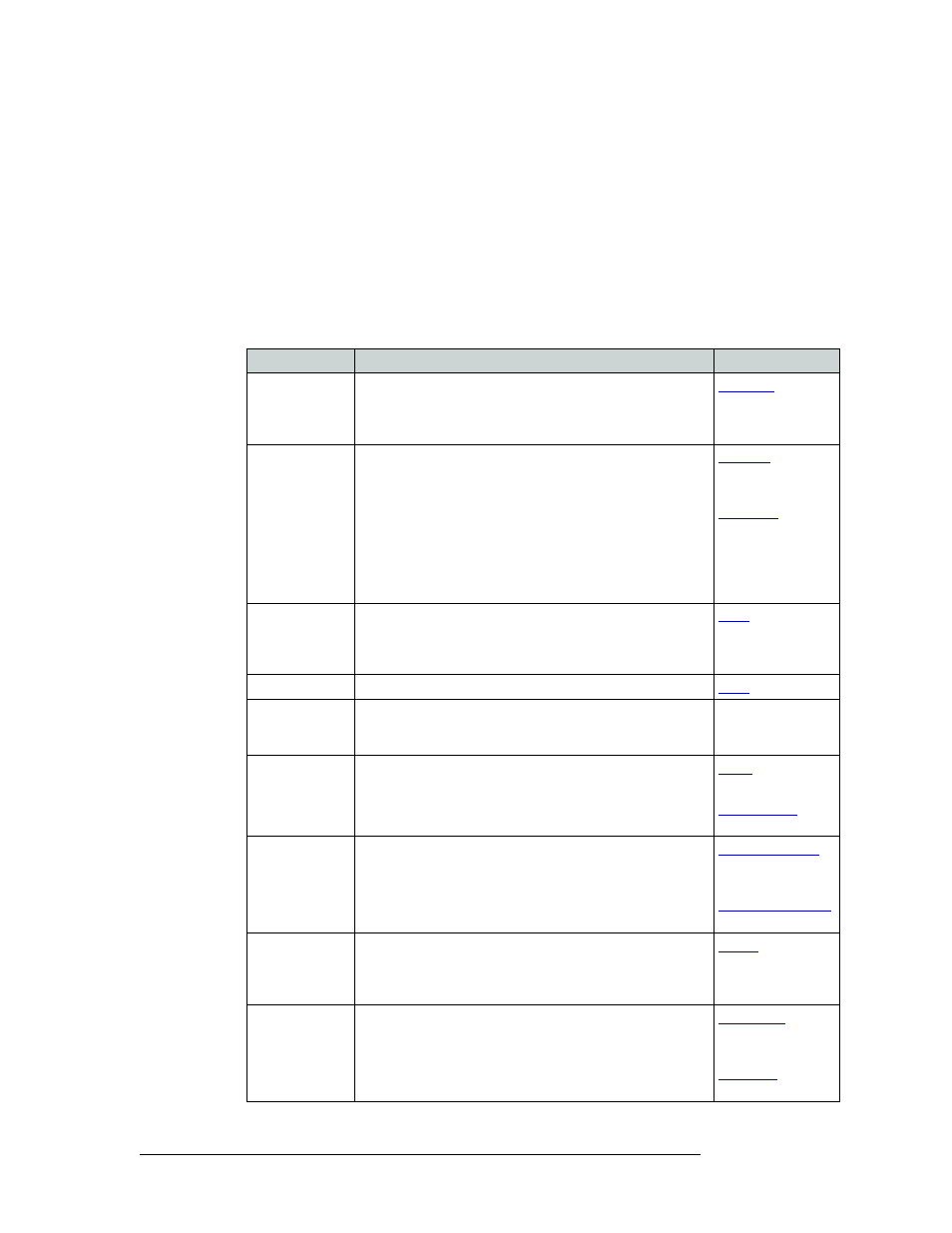
Select from the following button options:
Button
Description
Related Topic
Broadcast
On the data (control) level, assigns one controlling device
(master) to multiple controlled devices (slaves). Useful in
dubbing and editing applications. Status is only reported from
the first assigned slave.
Category
Selects a category (and its device list). Separate categories are
permitted for source and destination devices.
When you assign a category button, three additional drop-
down menus appear: ‘Source Category’, ‘Destination
Category’ and ‘Suffix’. Choose one of the categories (or none)
from the category lists. Choose one of the suffixes (or none)
from the suffix list.
Select a level from the ‘Level Set Filter’ to limit categories to
only those in the selected level.
359
and
Chop
When supported by the router, the button is a toggle that
enables and disables rapid switching of the selected
destination device between the current source and the preset
source. Used to test system timing.
Clear
Clears the last entry in a sequence of entries.
Destination
Sets the selected device as the default destination. When
selected, a drop-down list appears from which you can choose
the destination device.
—
Destination Lock Sets or removes a “lock” on current destination device. The
lock can only be removed at the control panel that originally
set the lock, or by a control panel that has “Force Release”
enabled.
and
Destination
Mode
This (required) button initiates the destination selection
sequence, and lights all valid category buttons in amber.
Operators choose the desired destination in XY mode, or the
destination to add in ‘Multidest’ mode.
on page 360
and
Destination
Protect
Sets or removes a “protect” on current destination device. The
protect can only be removed at the control panel that originally
set the protect, or by a control panel that has ‘Force Release’
enabled.
Free Source
Defines a phantom device that can be used to release or “free”
devices on the data (control) level. A free source is also used
with tielines to free the tieline for others to use. The free
source is configured in the Level Sets page.
361
and