Control panels – Grass Valley NV9000-SE v.3.0 User Manual
Page 269

NV9000-SE Utilities • User’s Guide
249
11. Control Panels
Adding a Control Panel
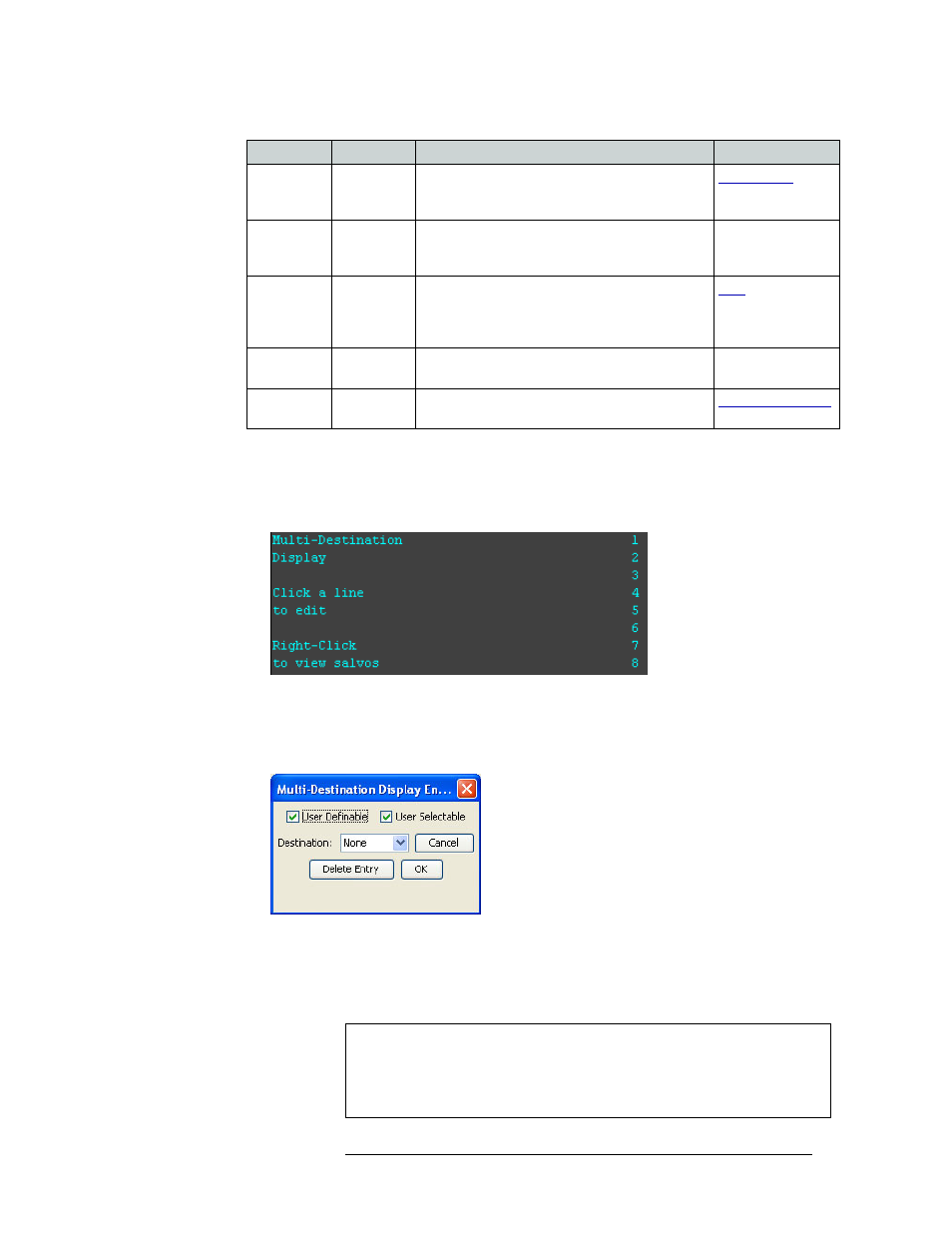
5 (For MD mode only) If the control panel window displays multi-destination lines, as shown in
Figure 11-7, edit the multi-destination display as needed:
a If “Multi-destination Display” is not currently displaying, as shown in Figure 11-7, right-
click on the control panel display window.
Figure 11-7. Panel Window Displaying Salvo Options
b Click on any line in the control panel to edit that line. Click
Page Down
to view additional
lines. The window displays 8 lines at any one time. The ‘Multi-Destination Display Entry’
dialog box appears:
Figure 11-8. Multi-Destination Display Entry Dialog Box
c Select if the line is ‘User Definable’ and/or ‘User Selectable’:
‘User Definable’ allows the operator to change a destination that appears in the display area.
Uncheck the ‘User Definable’ check box if the destination is to remain fixed.
Source Mode All modes
This (required) button initiates the source selection
sequence, and lights all valid category buttons in
green.
SrcDstMode All modes
Toggles between all buttons being sources or all
buttons being destinations, depending on the
current control panel mode.
—
Take
All modes
Switches the loaded preset source device(s) to the
selected destination device on all levels that have a
preset loaded. The ‘Status’ column changes to the
new device(s).
Undefined
--
Makes the button undefined and inactive. It will
remain unlit.
—
XY / MD
Mode
All modes
Switches control panel between XY and multi-
destination modes.
Button
Modes
Description
Related Topic
Note
When a multi-destination button is user definable, a
Destination Mode
but-
ton must be added to the control panel. This allows the user to select a new
destination from that location in the destination list using the category/
index buttons. If selected, the new destination is retained, even after reset.